There are many ways to find patterns in substation system loss data. One way is to use a statistical software package to create a regression model. This will allow you to identify which variables are most important in predicting system losses.
Another way is to plot the data and look for trends. This can be done by creating a line graph or scatter plot of the data. If there are any outliers, these can be investigated further to see if they are caused by an unusual event or if they represent a systemic problem.
Fiber Optic and Data Transferring between Substations and OTDR
- There are a few steps that can be taken in order to find patterns in substation system loss data: 1
- Review the data collected over time – This step involves reviewing all of the data that has been collected on substation system losses over a certain period of time
- This will give an overview of any patterns or trends that may be present
- Identify key indicators – After reviewing the data, certain indicators (e
- , peak times, days of the week, etc
- ) can be identified as being key factors in determining when system losses occur
- Analyze indicator data – Once key indicators have been identified, further analysis can be done on this data in order to better understand the patterns and trends associated with substation system losses
Electrical Substation Project Pdf
An electrical substation is a key part of the electricity infrastructure, serving as a hub where power lines from different parts of the grid meet and are connected. They come in all shapes and sizes, from small rural installations to large urban ones handling hundreds of megawatts of power.
Substations play a vital role in keeping the lights on and powering our homes and businesses, but they are often taken for granted.
That may be about to change, as substations are undergoing a digital transformation that is making them more complex, interconnected and vulnerable to cyberattacks.
A recent study by the National Academy of Sciences found that nearly two-thirds of U.S. electric utilities will need to upgrade their substations within the next 20 years just to keep up with rising demand and maintain reliability. The estimated price tag for these upgrades is $ 176 billion .
The good news is that many of these upgrades will bring much-needed improvements in efficiency and resilience. For example, some new substations will be equipped with advanced sensors that can detect problems before they cause outages, while others will use cutting-edge technologies like microgrids to keep critical services running during extended blackouts .
But along with these benefits come increased risks , as substations become more reliant on computer systems and communication networks that are vulnerable to cyberattacks .
In particular, there is growing concern about so-called ” Insider Threats ” – employees or contractors with malicious intent who have legitimate access to sensitive information or equipment .
To address this threat , utilities are working closely with government agencies and cybersecurity experts to develop best practices for protecting substations against cyberattacks . These efforts are critical not only for ensuring the reliable operation of our electricity grid , but also for safeguarding national security .
Substation Standards
There are a variety of substation standards in existence today, providing guidance for the design, construction, and operation of substations. These standards are developed by various organizations, including IEEE, IEC, and ANSI. While there is some overlap between these standards, each has its own focus and areas of expertise.
IEEE Standards: IEEE standards are published by the Institute of Electrical and Electronics Engineers. The IEEE Standards Association develops consensus-based standards across a wide range of industries. In the area of substations, IEEE covers a broad range of topics including general principles, equipment specifications, busbars, cabling systems, Earthing systems, metering and control systems, protection systems (including relays), transformers (power and distribution), switchgear (circuit breakers and disconnects), and reactors.
IEC Standards: IEC standards are published by the International Electrotechnical Commission. IEC standardization activities cover all fields of electrotechnology including electronic devices and components, power generation and distribution equipment as well as multimedia technology and information technology. In the area of substations specifically, IEC provides guidance on general principles; equipment specifications; installation requirements; cabling systems; Earthing arrangements; metering & control devices & circuits; protection devices & circuits; communication networks & protocols; safety requirements; testing methods & procedures.
ANSI Standards: ANSI standards are published by the American National Standards Institute. ANSI is a private non-profit organization that oversees the development of voluntary consensus standards for products manufactured in the United States.
Substation Manual
What is a substation?
A substation is an electrical facility where voltage is transformed from high to low, or the reverse, by means of transformers. Substations may also include switchgear, breakers, and other equipment necessary to control the flow of electricity.
Why do we need them?
Substations are a critical link in the power grid, providing the means to connect generation facilities with loads. They also provide a place to tap into the grid for customers who generate their own power, such as through solar panels.
How do they work?
Transformers are used to change the voltage of electricity passing through the substation. The primary winding of the transformer is connected to high-voltage transmission lines, while the secondary winding is connected to lower-voltage distribution lines.
This transformation makes it possible for electricity to be sent over long distances without losing too much energy along the way.
What are some common types of substations?
There are three main types of substations: transmission, distribution, and generation.
Transmission substations connect different parts of the power grid and step down voltages for distribution. Distribution substations distribute electricity at a lower voltage to homes and businesses. Generation substations connect power plants directly to transmission lines.
Distribution Systems And Substation Design
A distribution system is the network of transmission and distribution lines, substations, transformers and other equipment that delivers electric power from the generation source to individual customers. A well-designed distribution system ensures an adequate supply of electricity at a reasonable cost while minimizing service interruptions.
The first step in designing a distribution system is to determine the amount of power to be delivered to each customer.
The next step is to determine the route or path that the power will take from the generation source to the customer. The third step is to select the type and size of conductor that will carry the current along this route. The fourth step is to determine the location of substations and other equipment needed to support this conductor.
Once these steps have been completed, a detailed engineering design can begin.
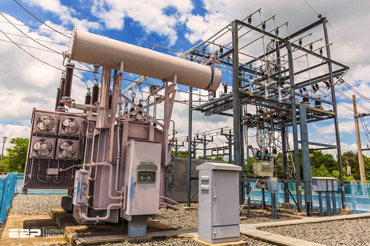
The purpose of a substation is to provide a safe place for workers to maintain electrical equipment, as well as a place where voltage can be increased or decreased as necessary. A typical substation contains high-voltage switchgear, low-voltage switchgear,transformers, circuit breakers and other equipment.
Substation Arrangement
A substation is a critical part of an electrical grid. It is a collection of equipment that receives power from generators, transforms it to a higher or lower voltage, and then sends it on to consumers. The substation arrangement refers to the physical layout of the equipment within the substation.
There are many factors that must be considered when designing a substation arrangement, such as the amount of space available, the types of transformers being used, the voltages involved, and the cooling requirements. In addition, the arrangement must take into account both operational and safety concerns.
Operational considerations include things like ease of maintenance and accessibility of equipment.
Safety concerns include minimizing exposure to high voltages and providing adequate ventilation for transformer rooms.
The most common type of substation layout is the radial configuration. In this setup, all incoming transmission lines converge on a single point known as the bus bar.
From there, power is distributed to individual transformers which step down the voltage for distribution to consumers.
While radial arrangements are very common, other designs may be more suitable in some cases. For example, if there is not enough space for a radial configuration or if additional reliability is desired, a looped configuration may be used instead.
In this type of substationlayout , transmission lines loop around several different transformers before exiting the substation . This provides redundancy in case one transformer goes offline .
Types of Electrical Substations Pdf
An electrical substation is a facility where electricity is generated, transformed, or distributed. The types of electrical substations pdf include transmission substations, distribution substations, and industrial substations. Transmission substations are used to connect the power grid to generating plants and load centers.
Distribution substations distribute electricity to end users such as homes and businesses. Industrial substations serve factories and other large consumers of electricity.
Substation Nomenclature
In a power system, a substation is a facility where voltage is transformed from high to low, or the reverse. The word substation comes from the days when such facilities were considered part of the distribution system. Today’s distribution systems are more complicated, and in many cases voltages are transformed multiple times.
A typical nomenclature for primary equipment in a substation would include the following:
– Substation bus – This is the “main line” to which all other equipment connects. Busbars may be made of copper or aluminum, and are supported on insulators.
In some cases, more than one bus bar may be used in order to provide redundancy or to supply different parts of the substation with different voltages.
– Circuit breakers – These devices protect equipment by opening and interrupting circuits as needed. They may be operated manually or automatically.
– Transformers – Transformers change (transform) voltage from one level to another. This can be done by either increasing or decreasing voltage levels. For example, a transformer could step up voltage from 120 volts (primary winding) to 240 volts (secondary winding).
Or, it could step down voltage from 13,800 volts (primary winding) to 480 volts (secondary winding).
– Capacitors and Reactors – Capacitors store energy in an electric field while reactors store energy in a magnetic field.

Credit: www.8newsnow.com
How Do You Calculate System Losses?
System losses are the difference between the amount of power that a system can generate and the amount of power that it actually does generate. The main factors that contribute to system losses are transmission and distribution losses, as well as generator, transformer and line losses. To calculate system losses, engineers first need to determine the efficiency of each component in the system.
Once they have this information, they can then use basic algebra to solve for the overall loss. For example, if we know that our transmission lines have an efficiency of 95% and our distribution lines have an efficiency of 98%, we can calculate our total system loss like this:
Total System Loss = (1-0.95) + (1-0.98)
= 0.05 + 0.02
How are Grid Losses Calculated?
Grid losses are calculated by taking the total amount of power that is generated by a power plant and subtracting the amount of power that actually reaches consumers. The difference between the two values is the grid loss. Grid losses can occur due to a variety of factors, including transmission line losses, transformer losses, and distribution system losses.
How Do You Calculate Technical Losses in a Distribution System?
Technical losses in a distribution system can be calculated using the American Society of Civil Engineers (ASCE) standard 7-10 method. This method uses the following equation:
L = K * (V^2/R) * I^2 * Z/S * 100%
Where L is the technical loss in percentage, K is a conductor loss factor, V is the phase voltage, R is the conductor resistance, I is the current flowing through the conductor, Z is the impedance of the system, and S is the number of phases.
For example, let’s say you have a 3-phase system with the following parameters:
Phase voltage: 240 V
Conductor resistance: 0.01 ohm/1000 ft
Current flowing through conductor: 1000 A
Impedance of system: 5 ohms
Using the ASCE 7-10 method, we would calculate technical losses as follows:
What is Distribution System Loss?
When electricity is generated at a power plant, it must travel through a distribution system to get to the customer. The distribution system includes transformers, wires, and poles that deliver the electricity from the substation to the customer. During this process, some of the electricity is lost due to resistance in the wires and other components in the system.
This loss is called “distribution system loss.”
There are two types of distribution system losses: technical losses and non-technical losses. Technical losses occur due to the physics of how electricity travels through wires (ohmic losses).
Non-technical losses are caused by factors such as theft or meter inaccuracies (commercial & administrative [C&A] losses).
In order to minimize technical loss, utilities use various methods such as line optimization and reactive power compensation. Line optimization involves placing equipment such as capacitors and voltage regulators at strategic points in the distribution system to improve voltage levels and reduce current flow.
Reactive power compensation uses devices like static VAR compensators (SVCs) and synchronous condensers (SCs) to supply or absorb reactive power so that less current flows through transmission lines, resulting in less energy lost as heat.
Utilities also focus on reducing C&A losses by implementing better metering systems and working with customers to prevent theft or fraudulent activity.
Conclusion
In order to find patterns in substation system loss data, it is important to first understand what this data represents. Substation system loss data can be defined as the amount of power lost between the generation point and the end user. This data can be represented through a variety of methods, including graphs, charts, and tables.
Once the data has been collected, it is important to analyze it in order to identify any patterns that may exist. There are a number of ways to do this, but some common methods include looking for trends over time or comparing different parts of the system. By understanding how to find patterns in substation system loss data, utilities can better manage their systems and improve efficiency.


