The voltage of a substation is the difference in electric potential between two points on the substation. The voltage at a substation is typically measured in volts (V).
In a power system, the voltage at which the equipment is operated is very important. The choice of voltage level for different parts of the system has a great influence on the economy of the overall system. In most cases it is desirable to operate the equipment at voltages as high as possible andtransform to lower voltages closer to the loads.
This results in reduced I2R losses in conductors and transformers.
However, there are other considerations that limit the choice of operating voltages. One such consideration is insulation strength.
Another consideration is that high voltages require greater clearances between conductors for safety reasons. The highest safe voltage for ground clearance purposes is about 36 kV. For these reasons, it is not practical to operate all parts of a power system at very high voltages.
The standard unit of voltage in electrical systems is the Volt (symbol: V). This unit was named in honor of Italian physicist Alessandro Volta (1745-1827), who invented the first battery (voltaic cell) in 1800.
One Volt is defined as the difference in potential between two points when one Ampere (A) of current flows through a conductor with resistance one Ohm (Ω), resulting in one Watt(W)of power dissipation:
What is Wave Trap| Capacitive Voltage Transformer | Transmission Lines Frequency | Hindi
What is Vct in Electrical?
VCT or voltage controlled tap is an electrical component that allows for the voltage drop across it to be varied. The resistance of VCTs can be varied by changing the applied voltage, which in turn alters the current flowing through the component. This makes VCTs ideal for use in applications where precise control over current flow is required, such as in electronic devices and circuits.
What Do Electrical Transformers Do?
An electrical transformer is a device that transfers energy from one circuit to another through inductively coupled conductors—the transformer’s coils. Transformers are used to increase or decrease the alternating voltages in electric power applications.
A typical transformer has two separate coils of wire wound around a common iron core.
The primary coil is connected to an AC power source, while the secondary coil is connected to the load. The alternating current flowing through the primary coil creates a magnetic field, which in turn induces a current in the secondary coil and powers the load.
Transformers come in a variety of shapes and sizes, and can be used for both commercial and industrial applications.
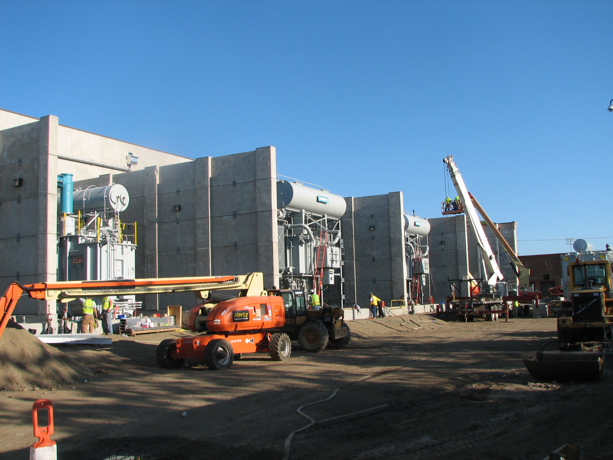
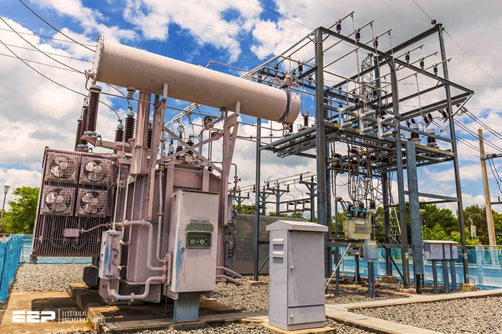
For example, large transformers are used in electrical substations to step down high-voltage transmission lines to lower voltages suitable for distribution to businesses and residences; small signal transformers are used inside electronic devices such as radios and televisions to couple stages of amplifiers together.

Credit: www.blcompanies.com
Conclusion
In a substation, the voltage is transformed from high to low or the vice versa. A typical substation has three stages of transformers- one primary transformer, one secondary transformer, and one tertiary transformer. The primary transformer steps down the voltage from the transmission line to a lower level so that it can be used by the secondary transformer.
The secondary transformer further steps down this voltage to an even lower level, which is then used by devices in the substation such as breakers, busbars, and instrument transformers. The tertiary transformer brings back up the voltage to its original level so that it can be fed back into the transmission line.


