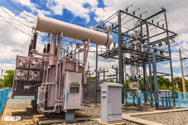
A substation is a collection of equipment for transforming, switching, or controlling the flow of electric energy in transmission and distribution systems. A typical substation includes voltage transformers, current transformers, circuit breakers, disconnect switches, busbars, and surge arrestors.
An electrical substation is a vital part of the power grid. It is where high-voltage electricity from power plants is transformed into the low-voltage electricity that powers our homes and businesses.
Substations come in all shapes and sizes, but they all have one thing in common: they are crucial to keeping the lights on.
without them, the flow of electricity would be interrupted, causing widespread blackouts.
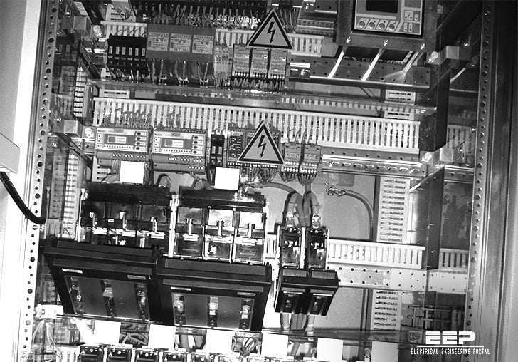
A substation typically consists of three main components: transformers, switchgear, and protection devices.Transformers change the voltage of the electricity so it can travel long distances through transmission lines before being reduced again at another substation closer to its final destination. Switchgear controls the flow of electricity through the substation and protects equipment from damaging surges.
Protection devices keep people safe by automatically shutting off power in the event of an emergency.
The size and complexity of a substation depends on many factors, including the voltage of the electricity it is handling and the amount of power required by its customers. Some substations are as small as a garage, while others occupy an entire city block.
EE-303 lecture 16: Single Line Diagram of 33kv/11kv sub station/BTER/How to draw /electrical study
Single Line Diagram of Power Distribution
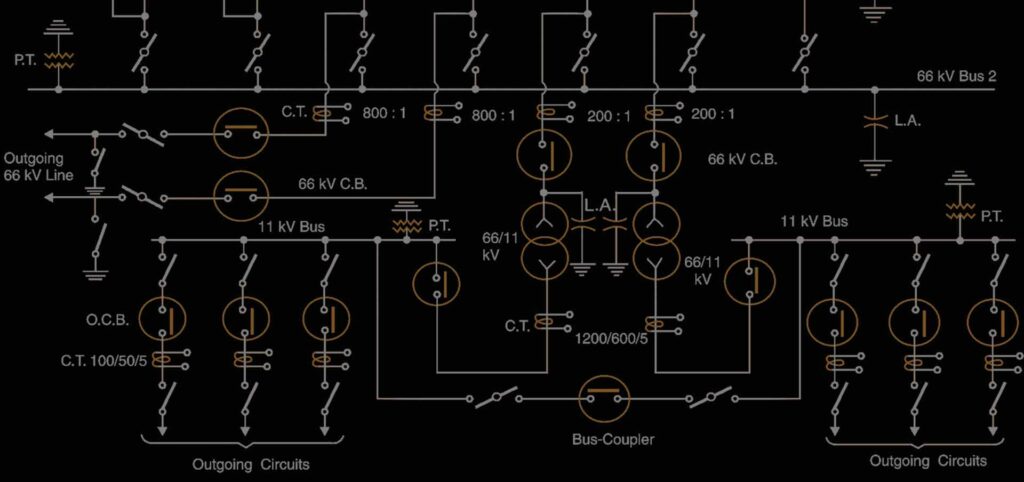
A single line diagram (SLD) is an important electrical engineering document that shows how power is distributed throughout a system. A typical SLD will show the main components of the system, such as transformers, circuit breakers, and buses, and how they are interconnected. It is also common for an SLD to include voltage and current ratings for each component.
An SLD is not only a valuable tool for engineers when designing or troubleshooting a power system, but it can also be used by non-engineers to gain a high-level understanding of how the system works. For example, if someone wants to know why their power went out during a storm, they can look at the SLD to see which components were damaged or destroyed by the storm.
Creating an accurate and up-to-date SLD is crucial for keeping a power system running smoothly.
Thankfully, there are many software programs available that make it easy to create and update an SLD.
Single Line Diagram of Electrical System
In an electrical system, a single line diagram (SLD) is the simplest way to show the major components of the system. It is a basic but essential tool for troubleshooting electrical problems. The SLD shows how these components are interconnected and can be used to determine which component is not functioning properly.
The SLD is divided into three sections:
The top section shows the utility company’s equipment including the transformer(s), main breaker, and secondary breakers. This section also includes metering devices that measure voltage, current, and power factor.
The middle section shows the customer’s equipment including service entrance equipment, main breaker, distribution panel boards, and branch circuit breakers or fuses. This section also includes any disconnect switches located between the customer’s equipment and the utility company’s equipment.
The bottom section shows grounding conductors that connect all of the metal parts of the electrical system together.
Grounding rods are driven into the earth to provide a low resistance path for any stray currents that may flow through the system.

Credit: www.cineticocargar.in
What is an Sld in Electrical?
An SLD is a short for “selective line discrimination” and refers to a type of electrical switchgear. This gear is used to protect against surges on the power line, by automatically disconnecting equipment when a surge occurs. The switchgear can be reset once the surge has subsided.
SLD’s are important in protecting electrical equipment from damage caused by power surges. They can be used in both residential and commercial settings. When choosing an SLD, it’s important to select one that is appropriate for the voltage and amperage of your system.
How Do You Study a Single-Line Diagram of Substation?
When studying a single line diagram of a substation, it is important to first understand the various symbols that are used. Once you have a good understanding of the symbolism, you can then begin to interpret the meaning of the diagram. The most important thing to remember when interpreting any type of electrical drawing is that electricity always takes the path of least resistance.
With this in mind, you can start to study the different elements of the substation diagram.
The first thing you will notice on a substation single line diagram is a large rectangle with all of the equipment inside of it. This rectangle represents the physical boundaries of the substation.
Within this rectangle, you will see several smaller rectangles which represent each piece of equipment within the substation. Each type of equipment will have its own symbol and these symbols are usually standardized across all drawings.
Some common pieces of equipment you will see inside a substation include:
-Transformers: These convert high voltage power from transmission lines into lower voltages used by distribution systems or industrial loads.
-Circuit breakers: These protect transformers, conductors, and other electrical equipment from damage due to overloads or short circuits.
-Capacitors: These store energy in an electric field and release it during periods of heavy demand on the system in order to improve power factor.
What is the Function of Sld?
The SLD (Second Level Domain) is the part of the domain name that comes after the dot. For example, in the domain name www.example.com, “example” is the SLD.
The function of an SLD is to give a unique identity to a website.
It’s like a fingerprint – no two websites can have the same SLD. This helps people find the right website when they’re looking for it online.
How Do You Draw an Electrical Sld?
An electrical single line diagram (SLD) is a drawing that shows the electrical circuits in a clear and simple way. It is usually used to show the layout of an electrical system, or to describe how electrical equipment is connected.
To draw an accurate SLD, you need to have a good understanding of how electricity works and be able to visualize the flow of electrons.
You also need to be familiar with symbols that represent different types of electrical components.
The first step is to create a basic outline of the SLD. This can be done by hand or using software such as AutoCAD.
Once the outline is complete, you can start adding in the various components that make up the electrical system. Each component will have its own symbol, which you can find in standard Electrical Engineering textbooks.
As you add each component, it’s important to label it clearly so that anyone looking at the SLD will know what it represents.
You should also indicate which direction electricity is flowing through each component. This can be done with arrows or by using different colors for positive and negative voltage levels.
Once all the components have been added, you can connect them together with lines to show how they are interconnected.
Again, it’s important to label each line so that anyone looking at the SLD knows what it represents.
Conclusion
An electrical substation is a key part of an electricity generation, transmission, and distribution system. Substations transform voltage from high to low, or the reverse, and perform many other important functions. Without substations, the power grid would not be able to function.


