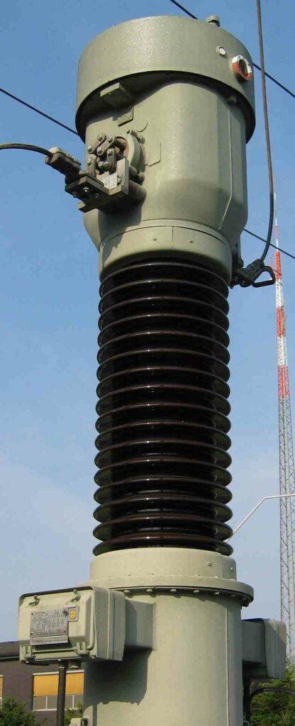
A current transformer is an instrument transformer that is used to measure alternating current (AC). It produces a current in its secondary winding that is proportional to the AC current in its primary winding. The primary winding of a current transformer is connected in series with the circuit whose AC current is to be measured.
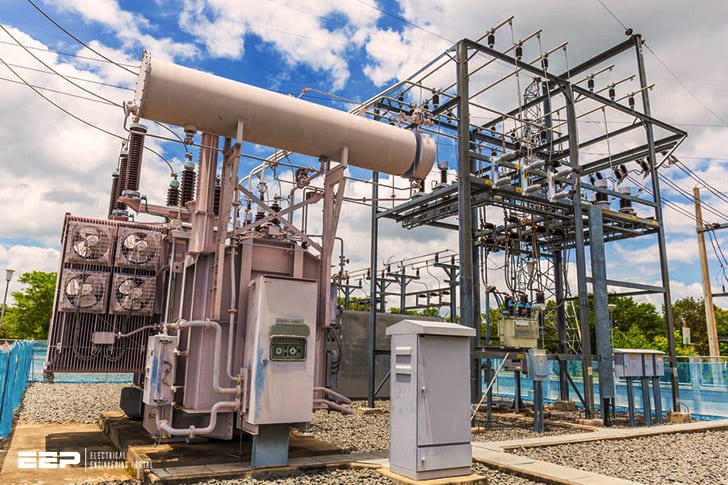
A current transformer is a type of transformer that is used in electrical substations to measure the current in a high-voltage circuit. It is an instrument transformer that transforms the high voltage, low current in the primary winding to a low voltage, high current in the secondary winding. This transformation allows for the measurement of currents that are too large to be measured directly by instruments such as ammeters.
Current transformers are used in a variety of applications, including power system protection, metering, and control. They are essential components of electrical substations and play a vital role in ensuring the safe and reliable operation of the power grid.
Types of Current Transformer in Substation
A current transformer is an instrument transformer, used for measurement of electric currents. It produces a current in its secondary winding proportional to the current flowing through its primary winding. It is an ideal transformer with respect to flux linkages between windings, but its turns ratio is not necessarily constant over a wide range of frequencies.
The secondary winding may have a different number of turns than the primary winding.
There are two main types of CTs: window type and bar type. The most common type of CT in use today is the window type, due to its lower leakage reactance.
Window Type CT: The construction of a window type CT is shown in Figure 1 below. It consists of a laminated iron core with primary and secondary windings wound on it. The primary winding is made from few turns (1-2) of thick conductor while secondary winding has many (100-5000) thin turns of conductor insulated from each other and from the core by varnish or paper layer(s).
A typical voltage rating for this kind of CT would be 2kV or less while currents can be as high as several thousand amperes under emergency conditions such as short circuits.
Function of Current Transformer in Substation
A current transformer is a type of transformer that is used to convert high-voltage, low-current electricity into low-voltage, high-current electricity. Current transformers are used in a variety of applications, including power plants, substations, and electrical distribution systems. Current transformers are designed to operate at specific voltages and currents.
The primary winding of a current transformer is typically connected to a high-voltage conductor, while the secondary winding is connected to a load or another device.
The function of a current transformer is to provide an accurate representation of the current flowing through the primary conductor for purposes of measurement or protection. For example, a current transformer can be used to measure the amount of current flowing through a high-voltage transmission line.
Additionally, current transformers can be used in conjunction with circuit breakers and other devices to protect equipment from damage due to excessive currents.
Current Transformer Working Principle
A current transformer is a type of transformer that is used to measure alternating current (AC). It produces a reduced voltage at its secondary winding proportional to the AC current flowing through its primary winding. Current transformers are used in metering and protection applications.
The working principle of a current transformer is based on Faraday’s law of induction, which states that an induced electromotive force (EMF) is generated in a conductor when there is a change in the magnetic flux linking the conductor. The direction of the EMF is given by Lenz’s law, which states that the EMF will oppose the change in flux. In a current transformer, an AC current flowing through the primary winding creates a magnetic field.
This magnetic field links with the secondary winding and induces an EMF in it. The magnitude of this EMF is proportional to the primary current and the number of turns in the secondary winding.
Current Transformer Pdf
A current transformer is a type of transformer that is used to measure alternating current (AC). It is used in electrical metering and protection applications. Current transformers are typically designed to have a low impedance so that they do not significantly distort the waveform of the measured AC signal.
The basic principle of operation for a current transformer is that it transforms the high current in the primary winding into a lower current in the secondary winding while maintaining the same voltage level. This allows for accurate measurement of AC currents without having to use high-current rated devices and wiring.
One common type of current transformer is the Rogowski coil.
This type of CT uses a helical windings around a non-magnetic core, which results in a very linear transformation ratio over a wide range of frequencies.
CTs are available in many different package types including split-core, ring core, and bar primary designs. The selection of an appropriate CT depends on many factors such as application, burden (the load on the secondary circuit), accuracy class, and environmental conditions.
Current Transformer Step-Up Or down
A current transformer is an instrument transformer that is used to measure alternating current (AC). It produces a reduced voltage proportional to the current in the circuit being measured. A basic current transformer consists of a primary winding and a secondary winding wrapped around a shared iron core.
The primary winding is connected in series with the circuit being measured, and the secondary winding is connected to the measuring instrument.
The ratio of primary turns to secondary turns determines whether the current transformer steps up or steps down the voltage. If the number of secondary turns is greater than the number of primary turns, then the voltage will be stepped up.
Conversely, if the number of primary turns is greater than the number of secondary turns, then the voltage will be stepped down.
Most current transformers have a turn ratio of 1:5 or 1:10, which means that for every volt applied to the primary winding, there will be 5 or 10 volts produced at the secondary winding. This allows for easy measurement of currents up to several thousand amps using standard voltmeters.
Current Transformer Working Principle Pdf
A current transformer is an instrument transformer that is used to measure alternating current (AC). It produces a scaled down version of the AC signal. The primary winding of the current transformer is connected in series with the conductor through which the AC flows.
The secondary winding is connected to the measuring instrument.
The working principle of a current transformer is based on electromagnetic induction. When AC flows through the primary winding, it creates a magnetic field.
This magnetic field induces a voltage in the secondary winding. The magnitude of this induced voltage is proportional to the magnitude of the primary current and number of turns in the secondary winding.
Current Transformer Connection
A current transformer is a type of transformer that is used to measure alternating current (AC). It consists of a primary winding, which is wrapped around the conductor that carries the AC, and a secondary winding. The secondary winding produces an AC voltage that is proportional to the current in the primary winding.
Current transformers are used in a variety of applications, including electrical metering and protection.
There are two main types of current transformers: wound and toroidal. Wound current transformers have a primary winding that is wound around a core made of iron or ferrite.
Toroidal current transformers have a primary winding that is wound around a ring-shaped core made of ferrite or iron powder.
Current transformers can be connected in either parallel or series. In parallel connection, the secondary windings are connected together so that they share the load equally.
In series connection, the secondary windings are connected so that the voltages add up. Series connection is typically used when there is more than one CT in use, such as in metering applications where multiple CTs are needed to measure different loads on the same circuit.

Credit: www.shutterstock.com
What is Current Transformer And How It Works?
A current transformer is a type of transformer that is used to convert high-voltage, high-current AC into low-voltage, low-current AC. The primary winding of the CT is connected in series with the circuit whose current is to be measured, and the secondary winding is connected to the measurement instrument.
The operation of a current transformer is based on Faraday’s law of electromagnetic induction, which states that a voltage will be induced in a conductor when there is a change in the magnetic field around it.
In a CT, the primary winding consists of many turns of conductor (usually copper or aluminum) wound around a ferromagnetic core. The secondary winding also consists of many turns wound around the same core. When AC flows through the primary winding, it creates a magnetic field around the core.
This changing magnetic field induces a voltage in the secondary winding.
Since the number of turns in the secondary winding is much greater than in the primary winding, the output voltage will be proportionally higher than the input voltage while still being proportional to it. For example, if there are 100 turns in the secondary winding and only 1 turn in the primary (all else being equal), then for every 1 volt induced intheprimarywindingtherewillbe100voltsinducedinthesecondarywinding—in other words, an amplification factorof100:1.(However, not alloftheinputvoltagewillbeseenattheoutputbecausethereis some “leakage” flux that does not pass throughthecoreandthusdoesnotinduceavoltageintheswindings.)
The ratio between primaries and secondaries can be stepped up or down as needed depending on what range of currents need to be measured; common ratios include 500:5 and 1000:1.
What is Ct And Pt in Substation?
CT and PT are two types of devices used in substations to measure electrical current and voltage, respectively. CTs (current transformers) are used to measure high currents, while PTs (potential transformers) are used to measure voltages. Both devices are essential for the proper operation of a substation.
Which Type Ct is Used Substation?
There are many different types of CTs that can be used in a substation, but the most common type is the Rogowski coil. This type of CT is used because it is very accurate and has a wide range of frequencies that it can measure. The Rogowski coil is also relatively easy to install and maintain.
Which is the Location of Current Transformer in Substation?
A current transformer is a type of transformer that is used to measure alternating current (AC). It is used in electrical engineering, particularly in measuring electricity. Current transformers are usually designed to have a large turns ratio so that the secondary current can be easily measured.
The primary winding of the transformer is connected in series with the circuit being measured so that all the current flowing through the circuit passes through the primary winding. The secondary winding of the transformer is connected to a measuring instrument such as an ammeter which measures the flow of current in the circuit.
The location of the current transformer in a substation will depend on the particular design of that substation.
However, it is typically located near or at the point where AC enters the substation, so that it can accurately measure incoming currents.
Introduction to Current Transformer | Video #7
Conclusion
A current transformer is a type of transformer that is used to measure electrical current. It is used in substations to measure the current flowing through high-voltage power lines. The transformer steps down the voltage so that it can be measured by an ammeter.


