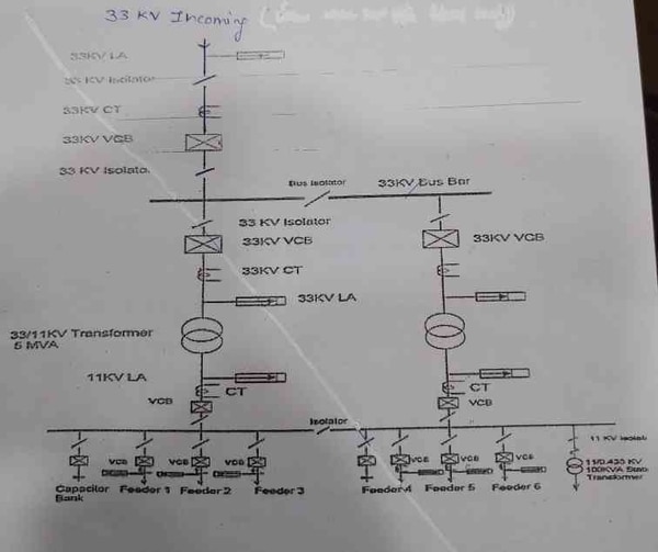
A single line diagram is a drawing that shows the electrical components of a substation in a simplified way. The diagram includes power lines, transformers, circuit breakers, and other equipment. It does not show the physical layout of the substation.
EE-303 lecture 16: Single Line Diagram of 33kv/11kv sub station/BTER/How to draw /electrical study
A single line diagram is a type of electrical drawing that shows the distribution of power throughout a substation. The purpose of this drawing is to provide a clear and concise overview of the distribution system so that engineers can easily identify problem areas and make necessary changes.
The 33 11Kv substation is one of the most common types of substations in use today.
This substation gets its name from the fact that it uses three-phase AC power at 11,000 volts. The 33 11Kv substation is typically used in medium to large scale operations such as factories, office buildings, and hospitals.
One advantage of using a single line diagram is that it clearly shows how each component in the system is interconnected.
This makes it easy to see where potential problems might occur and makes troubleshooting much simpler. Additionally, single line diagrams can be easily updated as changes are made to the system, making them an invaluable tool for keeping your distribution system running smoothly.
33Kv/11Kv Substation
Substations are an important part of the electricity grid. They help to increase or decrease the voltage of electricity as it flows through the grid, and can also be used to change the direction of current flow. 33Kv/11Kv substations are high-voltage substations that are typically used to connect two different parts of the grid, or to provide a connection between the grid and a large power generation facility.
33Kv/11Kv substations usually have a number of transformers, which are used to step up or step down the voltage as required. The transformer(s) at a 33Kv/11Kv substation will have a primary winding that is connected to the high-voltage side of the grid, and a secondary winding that is connected to the lower-voltage side of the grid. In some cases, there may also be tertiary windings that are used for special purposes such as metering or protection.
The transformers at a 33Kv/11Kv substation will typically have ratings in the range of 200 MVA to 800 MVA. This means that they can handle voltages up to 33 kilovolts on the primary side, and up to 11 kilovolts on the secondary side. The actual voltages present at any given time will be much lower than these maximum values, but the transformers must be able to withstand occasional surges without being damaged.
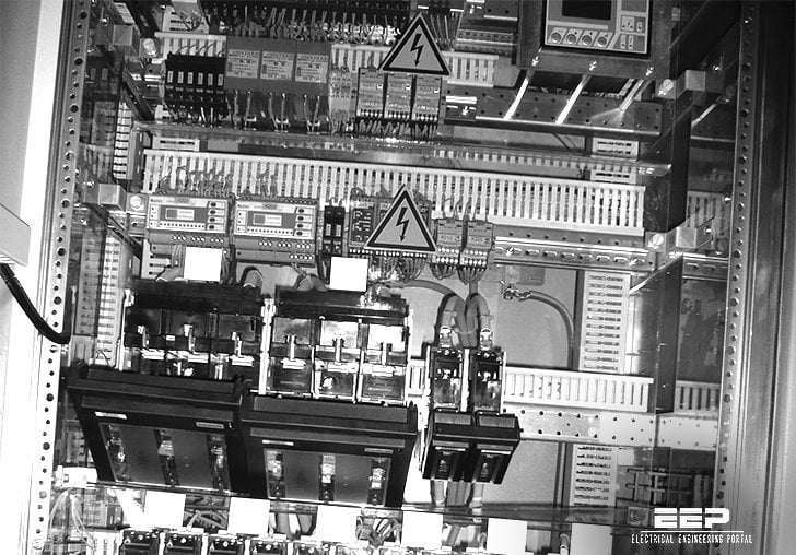
The layout of a 33kV/11kV substation will vary depending on its location and purpose, but there are some common features that all such substations share. For example, all 33kV/11kV substations will have one or more switchgear buildings where medium-voltage equipment is housed. This equipment includes circuit breakers and switches that are used to control electricity flow within the substation.
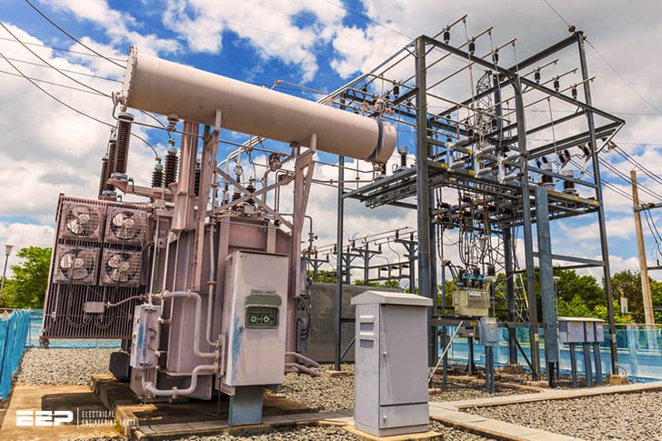
There will also usually be one or more outdoor areas where high-voltage equipment is installed; this may include things like power transformers and surge arrestors .

Credit: www.youtube.com
What is Single Line Diagram of Substation?
A single line diagram of a substation shows the equipment and connections in a simplified way that makes it easy to understand how the substation works. The single line diagram includes all of the components of the substation, including the transformer, circuit breakers, busbars, and meters.
How to Read Single Line Diagram of Substation?
A single line diagram of a substation shows the main components and their interconnections. The diagram includesTransformers, Transmission Lines, Circuit Breakers, Busbars, and other equipment. It does not show the detailed wiring inside the substation.
To read a single line diagram of a substation, first identify the different types of equipment shown on the diagram. Each type of equipment is represented by a symbol. The most common symbols are:
– Transformer: A transformer is used to change the voltage level of an electrical signal. The symbol for a transformer includes two circles connected by a zigzag line. The primary winding is shown on the left side and the secondary winding is shown on the right side.
– Transmission Line: A transmission line is used to carry electrical power from one point to another. The symbol for a transmission line looks like a straight horizontal line with arrows at each end indicating the direction of current flow.
– Circuit Breaker: A circuit breaker is used to protect electrical equipment from damage caused by overloads or short circuits.
The symbol for a circuit breaker includes two vertical lines connected by a horizontal bar.
– Busbar: A busbar is used to connect multiple pieces of electrical equipment together.
What are the Equipment in 33 11Kv Substation?
33/11kV substations are used to supply electricity to medium voltage networks. They are typically located at the end of a distribution network and provide a connection between the low voltage network and the high voltage network. A 33/11kV substation will usually contain the following equipment:
-A transformer to convert the incoming high voltage to a lower voltage that can be used by the distribution network.
-An earthing system to provide a safe path for any stray currents.
-A switchgear system to control the flow of electricity through the substation.
-Protective relays to monitor equipment and circuit conditions.
-Metering equipment to measure electrical parameters such as current, voltage and power factor.
What is the Difference between 33Kv And 11Kv Lines?
There are several important differences between 33kV and 11kV lines. For one, the voltage is much higher on a 33kV line, which means that it can carry more power than an 11kV line. This also means that a 33kV line must be thicker and stronger than an 11kV line in order to safely handle the increased voltage and power.
Finally, because of the increased voltage on a 33kV line, there is a greater risk of electrical hazards such as arc flash or fire. Therefore, workers who work on or near these lines must take extra precautions to ensure their safety.
Conclusion
A single line diagram of a 33/11kV substation is shown in the figure. The main components of the substation are:
– 33 kV incoming busbar
– 11 kV outgoing busbar
– Transformer
– Circuit breakers
– Isolators


