The power transformer is a key component in the substation and its proper operation is essential to the substation’s function. There are many potential problems that can occur with power transformers, but fortunately there are also many ways to solve them. The most common problem is an electrical fault, which can be caused by a variety of factors.
Once the cause of the fault is determined, it can usually be repaired or replaced. Other common problems include overheating, oil leaks, and mechanical damage. Most of these problems can be solved by following standard maintenance procedures.
- The first step is to identify the problem areas in the power transformer
- This can be done by conducting a visual inspection of the transformer and looking for any signs of damage
- Once the problem areas have been identified, the next step is to test the transformer to see if it is still functional
- This can be done by using a transformer tester or by taking measurements of the voltage and current output of the transformer
- If the transformer is found to be damaged, the next step is to repair or replace it
- This will usually involve hiring a qualified technician to do the work
- Once the repairs have been made, it is important to test the transformer again to ensure that it is working properly before putting it back into service
How Do Substations Work?
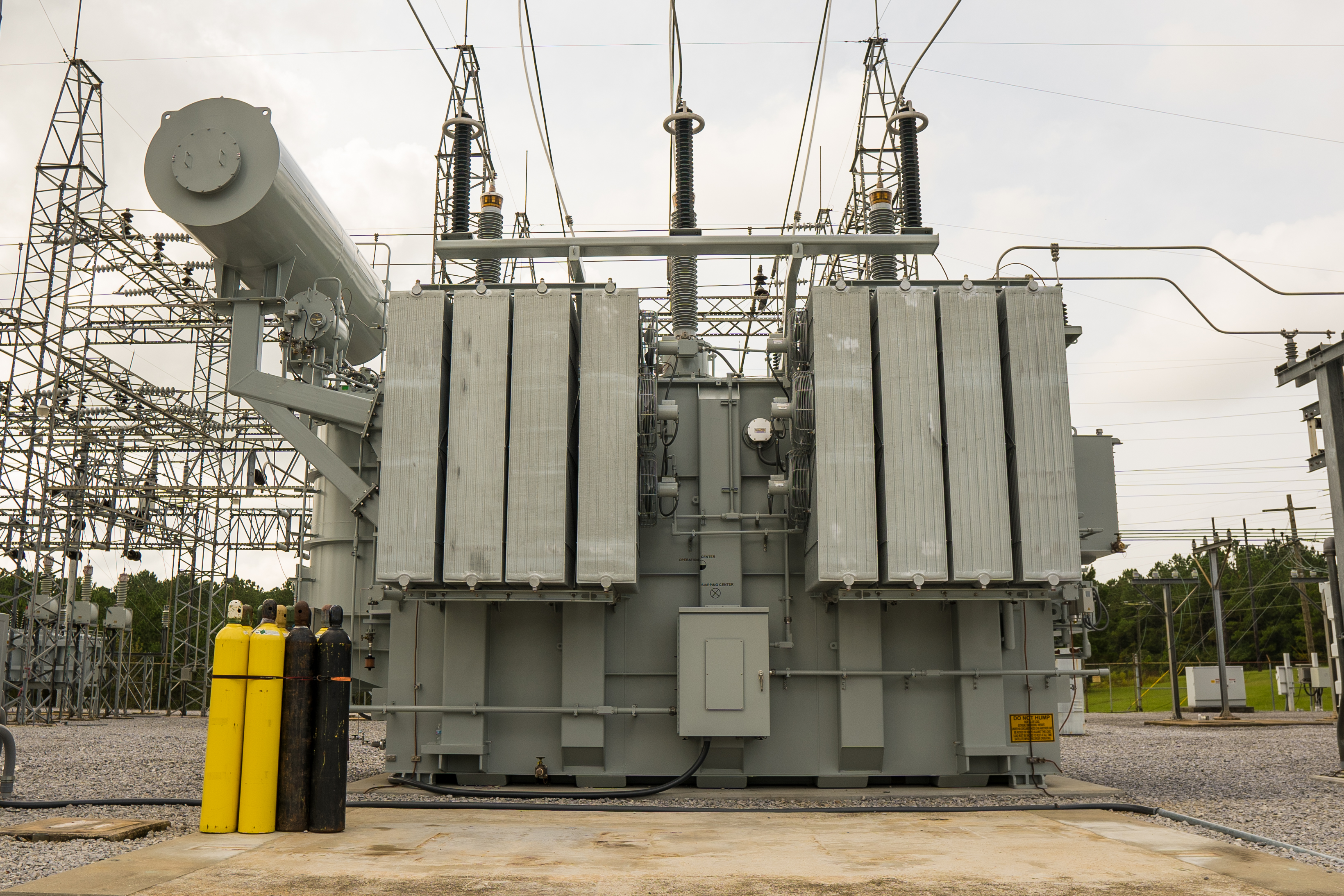
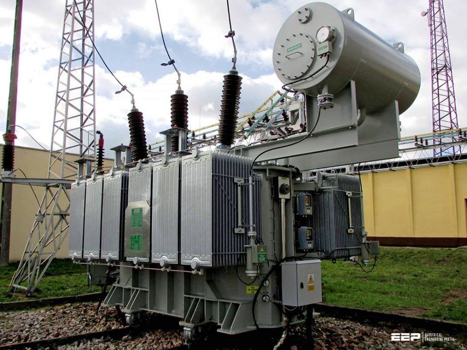
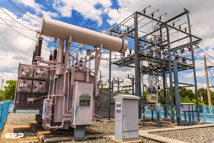
Power Transformer in Substation
A power transformer is a device that transfers energy between two or more circuits through electromagnetic induction. A power transformer can be used to change the voltage and current in an electrical circuit, and is commonly used in substations to step up or step down the voltages in transmission lines.
Function of Power Transformer in Substation
A power transformer is a device that helps to increase or decrease the voltages in an electrical circuit. It does this by transferring energy from one circuit to another through inductance or capacitance. A power transformer can be used in a substation to help control the voltage levels in the system.
By doing this, the transformer can help to improve the efficiency of power distribution and prevent damage to equipment.
Substation Ac Load Calculation
A substation is a critical part of the electrical grid, and the load calculation is a key part of ensuring its proper operation. The load calculation determines the amount of electricity that a substation can supply to customers without overloading the system.
The first step in performing a substation load calculation is to determine the maximum demand, or peak demand, for the substation.
This information can be obtained from past energy usage records or from projected future growth in demand. Once the maximum demand is known, various factors such as customer density, equipment efficiency, and line losses must be taken into account to determine the actual load on the substation.
It is important to perform regular load calculations on a substation to ensure that it continues to operate safely and efficiently.
If a substation becomes overloaded, it can lead to power outages and other problems for customers served by that substation. By regularly calculating and monitoring the loads on a substation, utilities can avoid these problems and keep their customers happy.
Transformer Troubleshooting Pdf
If you are having issues with your transformer, there are a few things that you can do to troubleshoot the problem. First, check to see if the transformer is receiving power. If it is not, make sure that the circuit breaker is turned on and that there are no loose connections.
Next, check the transformer’s output. If the voltage is too low or too high, adjust the tap changer accordingly. Finally, if the transformer is still not functioning properly, you may need to replace it.
Electrical Substation Design Calculations Pdf
In an electrical substation, the design calculations are very important in order to maintain a safe and reliable power system. There are many different types of substations, each with its own unique set of design challenges. In this blog post, we will focus on the calculations involved in designing a typical high-voltage substation.
The first step in any substation design is to determine the voltage levels that need to be supported. The voltage level will dictate the size and type of equipment needed. For example, a high-voltage substation will require larger transformers and other equipment than a low-voltage substation.
Once the voltage levels have been determined, the next step is to calculate the amount of power that needs to be handled by the substation. This information will be used to select the proper size transformer and other equipment.
After the transformer, the next most important piece of equipment in a substation is the switchgear.
Switchgear is used to control the flow of electricity within a substation. It is important to select switchgear that can handle the current and voltage levels required by the substation. Another key consideration for switchgear is its ability to withstand short circuit currents.
Short circuit currents can cause damage to equipment and pose a safety hazard, so it is important to choose switchgear that has a high short circuit rating.
Once all of the necessary equipment has been selected, it must be properly sized and configured for installation at the site. This process involves calculating things like clearances between pieces of equipment, cable sizes, and conduit sizes.
Failure And Troubleshooting of Transformer
When a transformer fails, it is important to troubleshoot the problem in order to determine the cause. There are many potential causes of transformer failure, including:
• Overloading: This is the most common cause of transformer failure.
When a transformer is overloaded, it can overheat and catch fire.
• Poor maintenance: If a transformer is not properly maintained, it can develop problems that lead to failure. For example, dirt and debris can build up on the coils and contacts, causing them to short circuit.
• Manufacturing defects: Sometimes, transformers fail due to defects in materials or workmanship.
Current Transformer in Substation
A current transformer is a type of transformer that is used to measure alternating current (AC). It is used in electrical engineering and power system applications. Current transformers are used to step down high voltage currents to a lower level so that they can be measured by devices such as ammeters, wattmeters, and protection relays.
The primary winding of a current transformer is connected in series with the circuit whose current is to be measured. The secondary winding has a much larger number of turns than the primary winding, which causes the secondary current to be proportional to the primary current.
Current transformers are classified according to their polarity, accuracy class, and nominal transformation ratio.
Polarity: There are two types of polarities used in CTs: direct-connected and reverse-connected. In direct-connected CTs, the primary and secondary windings are wound in the same direction; whereas in reverse-connected CTs, the primary and secondary windings are wound in opposite directions.
Accuracy class: Accuracy classes define the maximum permissible error at specified load conditions over a specified temperature range.
The most common classes used for CTs are 0.5, 1.0, 3.0, and 5P10; where P indicates percentage accuracy limit and 10 indicates tenths of a percent accuracy limit (e.g., 5P10 means five parts per ten thousand).

Credit: www.ge.com
How Do You Calculate Power Transformer?
There are a few different ways to calculate the power rating of a transformer. The most common way is to use the following formula:
P(transformer) = V(in) x I(out) x efficiency
Where:
P(transformer) is the power rating of the transformer in watts (W)
V(in) is the input voltage in volts (V)
I(out) is the output current in amps (A), and
efficiency is the percentage of electricity that is converted from one form to another by the transformer. For example, if a transformer has an efficiency of 80%, then it will convert 80% of the electricity that it receives into usable energy, and 20% will be lost as heat.
Another way to calculate transformer power loss is through No-Load Losses and Load Losses. No-load losses are caused by resistance in the windings and iron core, and load losses are caused by I2R losses due to current flowing through the windings. The total power loss for a transformer can be calculated using this formula: P(total loss)= P(no load loss)+ P(load loss).
To find just no-load or load losses, you would set P(no load loss)= 0 or P(loadloss)=0 respectively.
How Do You Calculate the Power of a Substation?
There are a few different ways that you can calculate the power of a substation. The first way is to use the voltage and current ratings of the equipment at the substation. This will give you a good estimate of the power output of the substation.
Another way to calculate the power output of a substation is to use the transformer capacity and efficiency. This method will give you a more accurate estimate of the power output of the substation.
How Do You Troubleshoot a Power Transformer?
A power transformer is a static device used to transfer electrical energy between two or more circuits. Transformers are used to change the voltage and current in an electric circuit. The most common use for transformers is to increase or decrease the voltage in an electric circuit.
There are two main types of power transformers: those that step-up voltages and those that step-down voltages. In a step-up transformer, the secondary winding has more turns than the primary winding. This increases the voltage across the secondary coil while decreasing the current flowing through it.
In a step-down transformer, the secondary winding has fewer turns than the primary winding, which decreases the voltage across it while increasing its current flow capacity.
When troubleshooting a power transformer, there are several things you can check for:
1) Check for loose or damaged connections – If any of the wires leading to or from the transformer are loose or damaged, this could be causing problems with its operation.
Make sure all connections are tight and secure, and if any wires are damaged, replace them with new ones.
2) Check for burnt out components – If any of the components inside the transformer have burnt out, this could also be causing problems. Replace any burnt out components with new ones.
3) Check for shorts – If there is a short circuit anywhere in the transformer’s wiring, this could also cause problems. Locate and repair any shorts before continuing further troubleshooting.
4) Check for open circuits – An open circuit anywhere in the transformer’s wiring can also cause problems.
How Do You Find the Current Transformer in a Substation?
To find the current transformer in a substation, you need to know the location of the primary and secondary windings. The primary winding is usually located near the center of the substation, while the secondary winding is located near the edge. Once you have located these two points, you can then use a measuring tape to find the exact location of the current transformer.
Conclusion
If you are having problems with your power transformer in a substation, there are a few things that you can do in order to solve the issue. First, check to see if the problem is with the primary or secondary winding of the transformer. If it is with the primary winding, you will need to replace the entire transformer.
However, if it is with the secondary winding, you may be able to repair it by rewinding the coil or replacing the damaged parts. In addition, you should also check for any loose connections and make sure that all of the fuses are intact.


