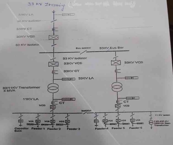
The 33/11kV substation is a type of electrical power supply system that uses alternating current. It is typically used to distribute electricity to smaller areas or as a backup power source. The single line diagram is a simplified representation of the various components and their interconnections in the substation.
A 33/11kV substation is a common voltage used in electrical power distribution. The 33kV refers to the line-to-line voltage and the 11kV refers to the line-to-neutral voltage. A typical 33/11kV substation would have a primary incoming voltage of 33,000 volts (33 kV) and a secondary outgoing voltage of 11,000 volts (11 kV).
The single line diagram is a basic representation of a substation showing the main components and how they are interconnected. This type of diagram does not show detailed information about individual components, but rather provides an overall view of the substation layout.
EE-303 lecture 16: Single Line Diagram of 33kv/11kv sub station/BTER/How to draw /electrical study
33/11Kv Substation Material List
Substations are an integral part of the electricity distribution system. They help to increase or decrease the voltage of electrical energy as it travels along the power grid. 33/11Kv substations are designed to step down the voltage from 33,000 volts to 11,000 volts.
This is typically done by using transformers.
There are a variety of materials that go into building a 33/11Kv substation. These include:
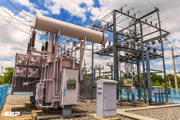
-Transformers: The transformer is the key component in a substation. It steps down the voltage from 33,000 volts to 11,000 volts. There are various types and sizes of transformers that can be used in a substation.
-Cables: Cables are used to connect the different parts of the substation. High-voltage cables are used to carry electricity from the transformer to the switchgear. Low-voltage cables are then used to connect the switchgear to devices like meters and circuit breakers.
-Switches: Switches allow for circuit breakers to be remotely operated. This helps protect equipment and personnel from high voltages.
-Busbars: Busbars help distribute electricity within the substation itself.

Credit: www.youtube.com
What is Single Line Diagram of Substation?
In power engineering, a single line diagram (SLD) is a type of simplified notation used to represent an electrical system. A typical SLD will show the major components of the system, such as generators, transformers, motors, and switchgear, along with the circuits connecting them. The SLD is the most basic type of electrical drawing and is usually used for preliminary planning purposes or for troubleshooting an existing system.
The purpose of a single line diagram is to provide a clear and simple picture of an electrical system that shows its basic elements and how they are connected. This can be useful when trying to understand how a system works or when diagnosing problems. Single line diagrams are typically drawn on large sheets of paper so that all the details can be seen at once.
A single line diagram does not usually show every detail of the system, but it should show all the major components and how they are connected. For example, if there is more than one generator in the system, each generator may be represented by a symbol instead of showing every individual wire connecting it to the rest of the system.
Some common symbols that are used in single line diagrams include:
– Generators: represented by a circle with three arrows coming out from it; often labeled G1, G2, etc.
– Transformers: shown as two rectangles side-by-side; often labeled T1, T2, etc.; may also have additional symbols inside them to indicate things like voltage levels
– Motors: shown as circles with wavy lines coming out from them; often labeled M1, M2 ,etc.
What is the Difference between 33Kv And 11Kv Lines?
There are many differences between 33kV and 11kV lines, the most important being voltage. 33kV lines have a much higher voltage than 11kV lines, meaning they can carry more power. This also means that 33kV lines are less likely to experience power outages and disruptions.
Another difference is the size of the conductor. The conductor on a 33kv line is much larger than on an 11kv line, which allows it to carry more current.
What is 33 11 Kv Transmission Line?
A 33 kV transmission line is a high voltage power line that is used to transmit electrical power from one point to another. The line consists of three phases, each phase carrying 11 kV of electricity. The total voltage of the line is 33 kV.
The transmission line is typically used to connect two substations, or to connect a substation to a generating station.
What is 33 11 Kv Substation?
A 33 kV substation is a high voltage electrical substation where the voltages are greater than 22kV. They are used to distribute electricity to areas of high demand. The equipment in a 33 kV substation includes:
-transformers
-circuit breakers
-disconnect switches
-cables
-busbars
The voltage in a 33 kV substation is transformed from the primary distribution voltage down to a lower secondary distribution voltage.
This is done using transformers. The secondary distribution voltage is then distributed to customers through cables and busbars.
Circuit breakers and disconnect switches are used to isolate parts of the system for maintenance or repair.
Conclusion
A 33/11kV substation is a type of electrical substation that transforms voltage from 11 kV to 33 kV. It is typically used in high-voltage power transmission systems. The substation includes a variety of components, such as transformers, switchgear, and circuit breakers.
The single line diagram is a graphical representation of the substation’s components and how they are interconnected.


