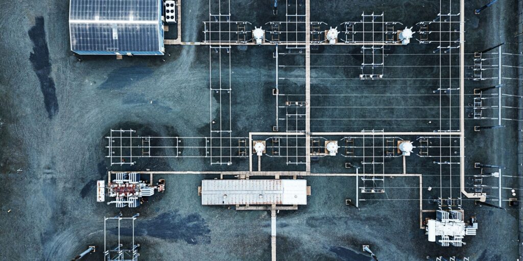
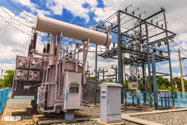
A circuit diagram of a substation shows the connections between the various pieces of equipment. This can include transformers, switchgear, circuit breakers, and other devices. The diagram will also show how these devices are interconnected and how they work together.
A substation is a crucial part of the electrical grid. It transforms voltage from high to low, or vice versa, and helps to regulate the flow of power. A well-designed substation will have a circuit diagram that clearly shows how it is interconnected.
Substations: Basic Principles | Circuit Breakers | Disconnectors | Relays | CTs & VTs | Arresters
66 Kv Substation Components
A 66 kV substation is a critical component in the electric power grid. It steps down high-voltage electricity from transmission lines to a lower voltage that can be used by distribution lines and customers.
A typical 66 kV substation includes several key components:
1. High-voltage switchgear: This includes circuit breakers, disconnect switches, and other equipment that controls the flow of electricity into and out of the substation.
2. Low-voltage switchgear: This switchgear steps down the voltage for use by distribution lines and customers. It typically includes transformers, circuit breakers, and other equipment.
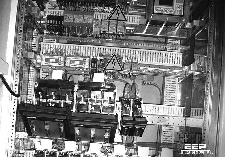
3. Protective relays: These devices monitor electrical conditions within the substation and automatically shut off power if there is a problem. This helps prevent damage to equipment and injuries to people.
4. Metering equipment: This measures the amount of electricity flowing through the substation so that it can be billed correctly.

Credit: electrical-engineering-portal.com
What is a Substation Diagram?
A substation diagram is a drawing that shows the relationship between the various parts of a substation. It is used to help understand how the substation works and to assist in its operation. The diagram may also be used for planning purposes, such as when adding new equipment or making changes to the existing layout.
A typical substation diagram includes a map of the site, showing the location of buildings, fencing, roads, and other features. Within the buildings, you will find equipment such as transformers, circuit breakers, and switchgear. The diagram will also show the connecting wires between these pieces of equipment.
The substation diagram provides important information about the electrical system. For example, it can show you what voltage levels are present at different points in the system. This is important information for safely operating the substation.
The diagram can also show you where faults may occur and how they can be isolated.
If you are working on or near a substation, it is important that you understand how to read a substation diagram.
What are the Three Main Parts of a Substation?
A substation is a critical part of the electrical grid. It serves as a gateway between different parts of the grid, and plays an important role in keeping the power flowing. The three main parts of a substation are:
1. The transformer: This is responsible for stepping up or down the voltage of electricity passing through it. This is done by changing the number of turns on the transformer’s coils. Transformers are essential for long-distance transmission, as they allow electricity to be transported over great distances without losing its strength.
2. The switchgear: This controls the flow of electricity within the substation and helps to protect equipment from damage due to sudden changes in voltage or current. Switchgear also makes it possible to isolate parts of the substation for maintenance without disrupting power supply to other parts of the grid.
3. The control room: This is where operators monitor and control the operations of the substation.
What is Single Line Diagram of Substation?
In power engineering, a single line diagram (SLD) is a type of schematic diagram used to show the connection between electrical equipment and components in a substation. The single line diagram is the basis for developing other types of diagrams and network analysis tools.
The single line diagram shows how each piece of equipment is connected to the others in the substation.
It gives information on voltage levels, circuit breakers, transformers, capacitors, buses, and more. The single line diagram can be used to develop control schemes and protection settings. It is also a valuable tool for troubleshooting problems in the substation.
How to Read Substation Single Line Diagram?
Most power system operators find it easiest to understand a substation single line diagram when it is drawn in an easily recognizable manner. The first step is to identify all of the major components of the substation and their functions. This will help you understand how each component affects the other components in the substation.
The next step is to identify all of the electrical equipment within the substation. Each piece of equipment will be represented by a specific symbol on the single line diagram. Once you have identified all of the equipment, you can begin to understand how they are interconnected.
Finally, you need to understand what each line on the single line diagram represents. These lines represent either conductor cables or busbars that carry electricity between different pieces of equipment within the substation. By understanding what each line represents, you can better understand how electricity flows through the substation.
Conclusion
A substation is a critical part of the electrical grid. It’s where high-voltage electricity coming from power plants is transformed into the low-voltage electricity used in homes and businesses.
A typical substation includes a transformer that steps down the voltage, switchgear to control the flow of electricity, and other equipment.
The exact configuration depends on the voltage levels involved and the type of substation.
Circuit breakers are used to protect equipment from damage caused by sudden surges in electrical current. When an overload or short circuit occurs, circuit breakers automatically shut off the flow of electricity to prevent damage.
Substations come in a variety of shapes and sizes, but all include some combination oftransformers, switchgear, and circuit breakers. By understanding how these components work together, we can keep the power flowing safely and reliably to homes and businesses around the world.


