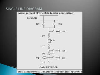
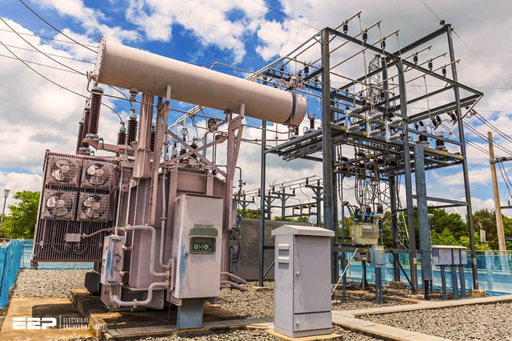
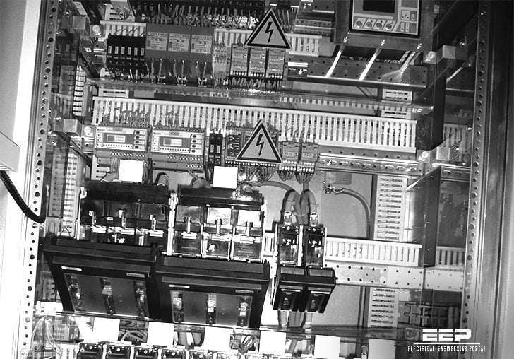
A single line diagram (SLD) is a type of electrical drawing that shows the important components of an air insulated substation (AIS). It is used as a guide for commissioning, maintenance, and troubleshooting purposes. The SLD typically contains information such as the voltage levels, equipment names, and protective device settings.
Single Line Diagram | Electrical Drawing | GIS Substation
An air insulated substation (AIS) is a type of substation in which the electrical equipment is not physically enclosed by any kind of enclosure. The word “air” in AIS refers to the fact that there is no solid barrier between the live parts of the equipment and the surrounding environment. This makes AIS potentially more dangerous than other types of substations, but also makes them cheaper and easier to maintain.
A typical AIS will have a number of different components, including:
– Transformers: These convert high voltage electricity into lower voltages, making it safe for use in homes and businesses.
– Circuit breakers: These protect transformers and other equipment from overloads by automatically disconnecting circuits when necessary.
– Capacitors: These store electric energy and help improve power quality by providing reactive power compensation.
– Disconnect switches: These provide a way to safely disconnect equipment from the power grid for maintenance or repair purposes.
Substation Single Line Diagram Explanation
A substation single line diagram is a graphical representation of a power system. It shows the components of the system and their interconnections. The single line diagram can be used to understand the operation of the system and to diagnose problems.

Credit: www.youtube.com
What is an Air Insulated Substation?
An air insulated substation (AIS) is a power substation in which the equipment is not mounted on an insulating medium, such as oil or paper. The conductors and other equipment are supported by structures, called line posts or towers, and they are separated from each other by air gaps. AIS was first used in 1882 when the Pearl Street Station in New York City, USA was built.
The main advantages of using AIS are that it has a lower initial cost than other types of substations and it is easier to maintain. In addition, AIS can be built in locations where space is limited. However, AIS has some disadvantages compared to other types of substations.
For example, because the equipment is not mounted on an insulating material, there is a greater risk of electrical faults occurring.
How Do You Read an Electrical Substation on a Single Line Diagram?
Assuming you want to know how to interpret a single line diagram of an electrical substation:
First, identify the components of the substation and what their function is. This will give you a good understanding of how the substation works overall.
Next, locate the main power source(s) and follow the path of power through the substation. Identify any transformers, breakers, or other devices along the way and note their functions. Finally, trace the path of power back to where it enters the system.
By doing this, you will have a good understanding of how power flows through the substation and can easily identify any potential issues.
What is Single Line Diagram of Substation?
A single line diagram of a substation is a drawing that shows the equipment and circuitry of the substation in a simplified way. This diagram does not show detailed information about the equipment, but it does show how the equipment is connected to each other. The single line diagram is useful for understanding the overall operation of the substation.
What is Difference between Ais And Gis Substation?
AIS and GIS substations are two types of power substations. AIS substations are air-insulated, while GIS substations are gas-insulated.
The main difference between AIS and GIS substations is the way in which they insulate the electrical equipment within the substation.
In an AIS substation, the equipment is insulated using air – either via air cooled transformers or by SF6 gas filled circuit breakers. By contrast, all of the equipment in a GIS substation is encapsulated within a sealed enclosure filled with an inert gas, typically SF6.
GIS technology was originally developed in Japan in the 1960s as a way to overcome some of the drawbacks of AIS substations, such as high land requirements (due to the need for large amounts of space to accommodate air cooled transformers) and susceptibility to weather conditions (such as storms).
However, GIS technology has become increasingly popular worldwide in recent years due to its many advantages over traditional AIS systems.
Some of these advantages include:
– Reduced land requirements: due to their compact design, GIS substations can be built on smaller plots of land than AIS Substations;
– Increased reliability: because all of the electrical equipment is sealed within a container filled with an inert gas, there is no risk of fire or explosion;
– Improved safety: due to their enclosed design, there is no need for personnel to enter the danger zone around live electrical equipment;
– Reduced maintenance costs: since there is no need for regular cleaning or painting, maintenance costs are lower than for traditional AIS systems;
Overall, GIS technology offers a number of advantages over traditional AIS systems – however it should be noted that both technologies have their own strengths and weaknesses depending on specific application needs.
Conclusion
An air insulated substation (AIS) is a substation where the equipment is not physically touch each other. The elements are separated by air and they use air as an insulating medium. A typical AIS layout consists of a number of busbars, circuit breakers, transformers, and other devices connected together by means of metal-enclosed switchgear.
A single line diagram (SLD) is a type of schematic diagram that shows the single phase or three phase AC power system on one side and the distribution system on the other side. It shows how the electrical components are connected to each other. The SLD does not show any wiring details but it does show the relative locations of the various components.


