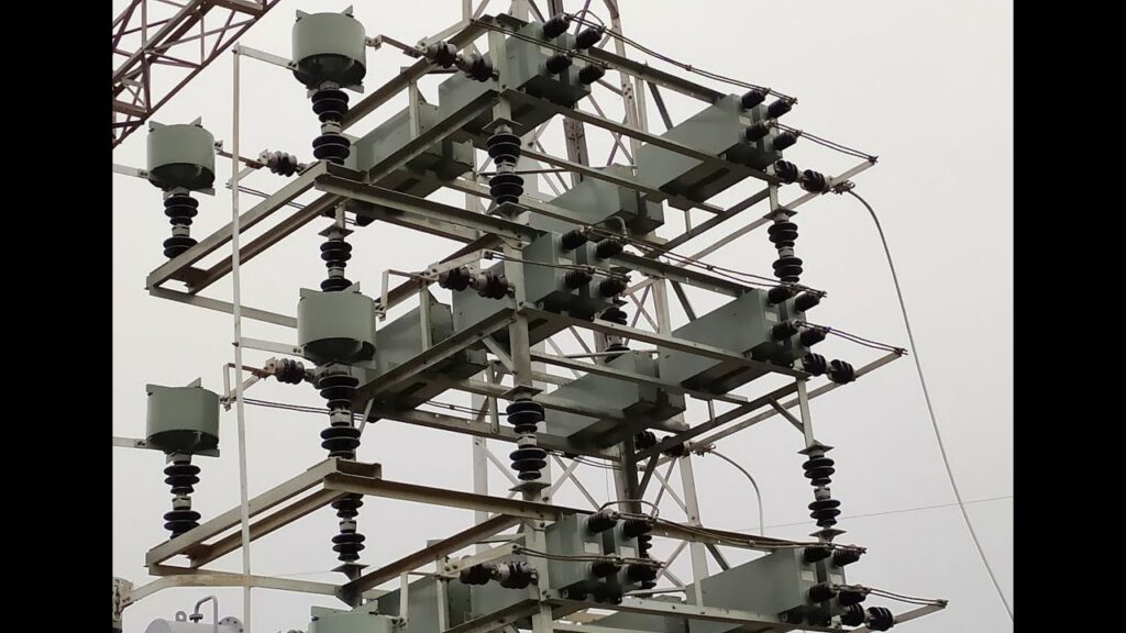
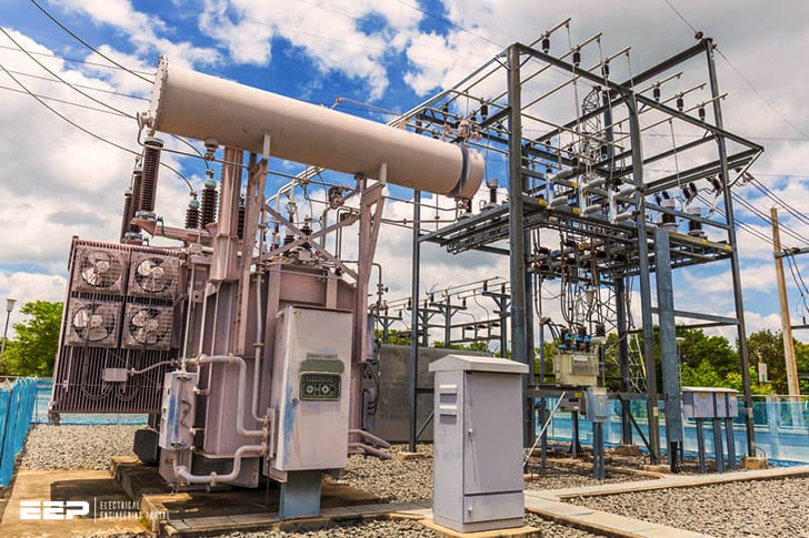
A capacitor bank is a device that stores electrical energy in the form of an electrostatic field. It is composed of one or more capacitors that are connected in parallel or series, and often used to improve power factor or provide reactive power compensation. Capacitor banks are used in a variety of applications, including power plants, transmission and distribution systems, industrial facilities, and consumer electronics.
Capacitor bank | Full details in HINDI | 33/11 KV substation capacitor bank
A 33 11Kv substation generally has a capacitor bank to improve the power factor and reduce line losses. The capacitor bank may also be used to improve voltage regulation.
Capacitor Bank in Substation Pdf
A capacitor bank is a device that stores energy in the form of electrical charge. It is typically used in electric power systems to improve system stability and power quality. A capacitor bank can be used to smooth out voltage fluctuations, provide reactive power compensation, or both.
A typical capacitor bank consists of a number of individual capacitors connected together in parallel or series-parallel configuration. The size of the capacitor bank depends on the specific application and the amount of reactive power compensation required. Capacitor banks are often used in substations, where they are connected to the high-voltage busbars.
Capacitor banks can provide several benefits to an electric power system:
• They can improve system stability by mitigating voltage fluctuations caused by load changes or faults.
• They can increase power quality by reducing harmonic distortion and providing reactive power compensation.
• They can help reduce line losses by providing reactive power compensation.
33Kv Capacitor Bank Specification
33kv capacitor banks are used to provide power factor correction and improve the efficiency of electrical systems. They are usually installed at the distribution level, between the transformer and the load. The capacitors are connected in series or parallel across the line to be corrected.
When selecting a 33kV capacitor bank, it is important to consider the required rating of each individual capacitor unit in order to meet the system specification. The table below outlines the various ratings that may be required:
-Voltage: 33kV
-Frequency: 50 or 60Hz
-Capacitance: 3 – 400 kvar (3 steps)
-Connection Type: Star (wye) or delta
The most common 33kv capacitor bank specifications are based on a three phase system with a voltage of 33,000 volts. This system can either be operated at 50 hertz or 60 hertz with a capacitance from 3 to 400 kilovar. In terms of connection type, star (wye) or delta methods can be employed although some banks will have both options available for extra flexibility.
11Kv Capacitor Bank Specification
A capacitor bank is a device that stores electrical energy in the form of capacitance. A capacitor bank can be used to provide power to an electrical system during a power outage, or to help regulate the voltage in an electrical system. The most common type of capacitor bank is the 11Kv capacitor bank.
The 11Kv capacitor banks are designed to store energy at a voltage of 11,000 volts. These banks typically have a capacitance of 1 farad per volt, meaning that they can store up to 11,000 farads of charge. The banks are made up of many individual capacitors, which are connected in series and parallel to create the desired capacitance.
The number of capacitors in a bank will vary depending on the manufacturer and the specific application for which the bank is being used.
The size and weight of 11Kv capacitor banks can vary significantly, depending on the manufacturer and the specific application for which the bank is being used. These banks typically range from about 10 pounds (4.5 kilograms) to several hundred pounds (about 90 kilograms).
Capacitor Bank in Substation Wikipedia
Substation Wikipedia
In electrical engineering, a substation is a component of an electricity supply system which transforms voltage from high to low, or the reverse, or performs any of several other important functions. Between the generating station and consumer, electric power may flow through several substations at different voltages.
A substation may include transformers to change voltage levels between high transmission voltages and lower distribution voltages, or at the interconnection of two different transmission voltages.
A capacitor bank is typically used in electric power systems to improve power factor by providing reactive power compensation. Capacitor banks are also used for voltage stabilization, harmonic filtering and control (including grid code compliance), and as emergency backup supplies of reactive power (curtailment).
Capacitor banks are made up of individual capacitors connected in parallel and/or series circuits depending on the required application. The size of each capacitor within the bank is dependent on many factors including but not limited to system voltage, current harmonics present, desired life of equipment, etc.
The most common connection for shunt capacitor banks is delta because it has several advantages over other arrangements: better utilization of space due to smaller conductor sizes; improved regulation because there is no zero-sequence impedance in the circuit; higher reliability because if one phase is lost there is still some compensation available; and ease of maintenance because only two phases need be disconnected at any one time for maintenance purposes.
11Kv Capacitor Bank Manufacturer
As an 11Kv capacitor bank manufacturer, we know that the correct installation and maintenance of your equipment is critical to its performance. We offer a full range of services to support our products, including on-site commissioning, training and technical support. Our team of experts can provide you with the knowledge and advice you need to ensure your system is installed correctly and performing at its best.
Capacitor Bank Working Principle
A capacitor is a device that stores electrical energy in an electric field. It is composed of two conductors separated by a dielectric (insulator). The conductors are usually metal plates, and the dielectric can be either air or a solid material.
When an electric potential difference exists between the two conductors, an electric field develops across the dielectric. This field stores energy as electrostatic potential energy, which is sometimes called “capacitance.”
The amount of charge that can be stored on the plates of a capacitor is determined by its capacitance.
The SI unit for capacitance is the farad (F), which is defined as one coulomb per volt (C/V). A 1-farad capacitor can store 1 coulomb of charge at 1 volt.
The capacitance of a capacitor depends on several factors, including the size and shape of the plates, the type of dielectric material between them, and the distance between them.
A larger plate area results in more storage capacity; however, if the plates are too close together, they will begin to interact magnetically and their efficiency will decrease. Dielectrics with a higher permittivity tend to increase capacitance; however, using a dielectric with too high of a permittivity can cause problems with leakage current. The spacing between conductor plates also affects capacitance—a smaller distance means more storage capacity but again may cause issues with leakage current.
Ultimately, there is an optimal combination of these variables that results in maximum efficiency for any given application.
Capacitors are used in many electronic devices such as radios, televisions, computers, and motor controls because they can store large amounts of electrical energy very efficiently.
Capacitor Bank Calculation
As an electrical engineer, you may be asked to calculate the size of a capacitor bank. This is not a difficult task, but there are several factors that must be considered in order to do it accurately.
The first step is to determine the voltage of the system.
This will determine the capacitance required for the bank. The next step is to calculate the current flowing through the system. This will help you determine how many capacitors are needed in order to provide adequate power storage.
Once you have these two numbers, you can then multiply them together to get the total capacitance required for your system. After that, you’ll need to decide on a suitable voltage rating for your capacitors. Once again, this will be based on the voltage of your system.
Finally, you’ll need to choose a brand and model for your capacitor bank. There are many different types available on the market today, so it’s important to do some research before making your final decision. With all of these factors taken into account, calculating the size of a capacitor bank is relatively simple task.

Credit: www.indiamart.com
When Capacitor Banks are Used in Substations?
Capacitor banks are used in substations for a variety of purposes. The primary purpose is to improve the power factor by storing energy and releasing it when needed. This results in improved efficiency and reduced losses.
Additionally, capacitor banks can provide reactive power support, voltage stabilization, and flicker mitigation.
Where is Location of Capacitor Banks in an Indoor Substation?
Capacitor banks are devices that are used to store electrical energy in the form of an electrostatic field. They are found in a variety of applications, including power plants, transmission and distribution systems, and renewable energy systems. In an indoor substation, capacitor banks are typically located near the transformers.
Where are Capacitor Bank Installed?
There are many places where capacitor banks can be installed. They are often used to improve the power factor of an electrical system, or to provide reactive power support. Capacitor banks can also be used for voltage correction, or to help stabilize a system during load changes.
What Does a Capacitor Bank Do on a Distribution System?
A capacitor bank is an electrical device that stores energy in the form of electric charge. It is composed of a group of capacitors connected in parallel or series, or both. Capacitor banks are used to correct power factor and improve the efficiency of electrical systems by storing energy during periods of low demand and releasing it during peak demand periods.
Conclusion
A 33 11Kv substation uses a capacitor bank to improve the power factor and voltage of the system. The capacitor bank is made up of three phases, each with its own independent capacitors. The total capacitance of the bank is 33,000 microfarads.
The capacitor bank is used to improve the power factor by reducing the reactive power demand of the system. It also improves voltage by providing a more uniform voltage across all three phases.


