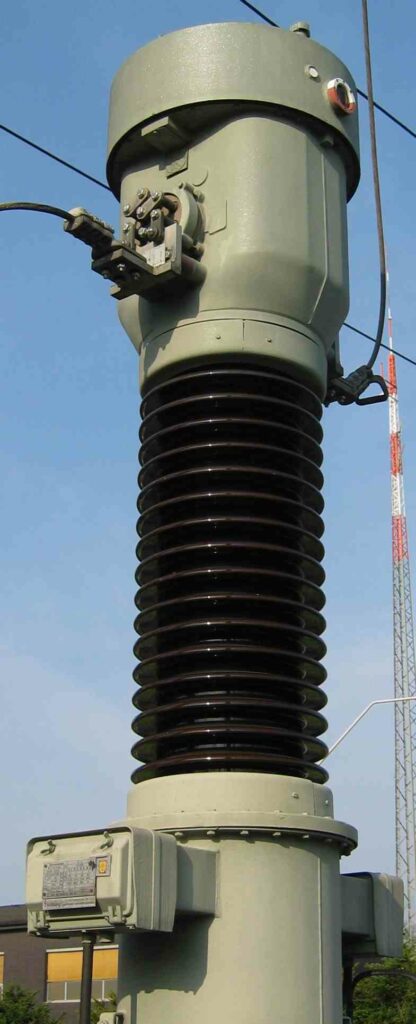
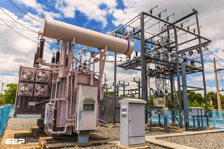
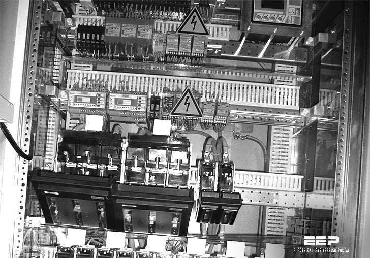
The main function of the current transformer is to step down the high voltage from the primary winding to a safe and manageable level on the secondary winding that can be safely handled by electrical devices. The purpose of the potential transformer is to step down the high voltage on the primary side to a lower, safer voltage on the secondary side. This allows for accurate measurements to be taken of the voltages within the substation without putting workers in danger.
The function of a Ct is to provide electrical isolation between two or more circuits by physically encapsulating the conductor in an insulating material. The function of a Pt is to provide an accurate measure of voltage or current in a circuit.
How to identify CT and PT in substation ? | बिना Name Plate के कैसे CT और PT पहचाने ?
Function of Current Transformer
A current transformer is an electrical device that is used to measure alternating current (AC). It consists of a primary winding and a secondary winding. The primary winding is connected in series with the circuit that is being measured.
The secondary winding is connected to a meter or other measuring device.
The primary purpose of a current transformer is to provide a safe, convenient way to measure AC currents. Current transformers are used in many applications, including utility metering and protection, industrial process control, and instrumentation.
When used for metering, current transformers are typically installed near the main service entrance of a building or at the point where power is delivered to equipment. They are also used in distribution panels and switchgear. For protection applications,current transformers are usually installed near potential sources of fault currents, such as motors and generators.
Current transformers can be classified by their construction, function, or use. Construction wise, they may be air-core , toroidal , or laminated . Functional classification may be either isolation or potential .
Isolation type CTs provide galvanic isolation between the primary and secondary circuits while potential type CTs do not provide this isolation. Application classification may be either indoor or outdoor .
The most common type of current transformer is the iron-coreCT.
Iron-core CTs have a coil of wire wrapped around an iron core. The iron core provides a path for the magnetic flux created by the primary current flowing through the coil of wire (the primary winding). This flux couples theprimary winding to the secondary winding, which is wound on top ofthe primary winding (Figure 1).
The number of turns in thesecondary winding determines the transformation ratioof the CT; thatis, it determines how much larger (or smaller)the secondarycurrent will be than theprimarycurrent flowing throughthe coilofwire.
C.T. And P.T. are Used for
C.T. And P.T. are Used for .
If you’ve ever had a physical therapist or chiropractor work on your back, neck, or other joints, you may have heard them use the terms “C.T.” and “P.T.” These abbreviations stand for “cervical traction” and “pelvic traction,” respectively.
Both of these treatments involve the use of weights and pulleys to stretch and align the spine. Cervical traction is usually used to treat pain in the neck and upper back, while pelvic traction is used to treat pain in the lower back and pelvis.
These treatments can be very effective in relieving pain and restoring normal movement to the spine.
If you think you might benefit from either of these treatments, talk to your doctor or physical therapist about whether they might be right for you.
Potential Transformer Pdf
A potential transformer is a type of transformer that is used to isolate the high voltages in electrical power systems. Potential transformers are used to step down the voltage in order to measure it or to provide a low voltage supply for relays and meters.
Potential transformers (PTs) are also known as voltage transformers (VTs).
A VT is an instrument transformer in which the primary winding has many turns and the secondary winding has few turns. The primary purpose of a PT is to step-down system voltages so that metering or other devices can be operated at a lower, safer voltage level. Other purposes include providing isolation between circuits, matching impedance levels, and providing current limiting.
The most common use of potential transformers is for sensing line voltage in power systems. They may have either single-phase or three-phase primaries with corresponding single-phase or three-phase secondaries. Most PT’s have vector groupings which allow them to be used on either wye (Y) or delta (Δ) connected systems without phase shift error.
As with all types oftransformers, potentialtransformers must be sized accordingto the highest anticipatedsystemvoltageandcurrentthat theywill experiencein service.They arealso selectedon the basisof theiraccuracyclassificationwhichdictatestheir allowedpercentagetolerance bandwidthandthe numberof secondaryturns neededto produceone volt RMSon theirsecondarywindingunderfull RatedLoad conditions(usually100%).
Potential Transformer
A potential transformer is a type of transformer that is used to measure voltage. It is also known as a voltmeter. Potential transformers are used in electrical systems to step down high voltages so that they can be measured by lower-voltage instruments, such as wattmeters and ammeters.
Potential transformers are made up of two coils of wire wound around a common iron core. The primary coil has more turns than the secondary coil. This means that the potential transformer steps down the voltage from the primary winding to the secondary winding.
The current in the primary winding remains the same as in the secondary winding because there is no loss of power in the transformer.
The output of a potential transformer can be taken from either the secondary winding or the tertiary winding. The tertiary winding is often used for monitoring purposes only and is not connected to any load.
The advantage of using a potential transformer over an ordinary transformer is that it does not require a separate power supply; it draws its power from the circuit being measured.
Potential transformers are used in many applications, such as:
-Instrumentation circuits
-Protective relays
Current Transformer And Potential Transformer
A current transformer (CT) is a type of transformer that is used to measure alternating current (AC). It produces a scaled-down version of the AC signal, which can be used to measure the current flowing through a conductor. A potential transformer (PT) is a type of transformer that is used to measure voltage.
It produces a scaled-down version of the AC signal, which can be used to measure the voltage across a conductor.
Ct Pt Transformer
A CT PT transformer is a type of transformer that is used to change the current and voltage in an electrical system. It is made up of two parts: the primary winding and the secondary winding. The primary winding is wound around a metal core, while the secondary winding is wound around a secondary coil.
The two windings are connected together at one end, and the other end of each winding is connected to a different terminal.
The primary purpose of a CT PT transformer is to change the current and voltage in an electrical system so that it can be used more efficiently. For example, if you have an electrical system that uses DC power, you can use a CT PT transformer to convert it to AC power.
This way, you can use less energy overall and save money on your electric bill.
Another benefit of using a CT PT transformer is that it can help protect your equipment from damage. If there is ever a sudden surge of electricity, the transformer will act as a buffer between your equipment and the surge.
This can prevent your equipment from being damaged or destroyed by an unexpected spike in voltage.
If you are thinking about using a CT PT transformer in your electrical system, there are several things you need to keep in mind. First, make sure that you understand how they work and what their capabilities are.
Second, be sure to choose the right size for your particular application. Third, be sure to follow all safety instructions when installing or using them.
Ct And Pt Difference
If you’re confused about the difference between CT and PT, you’re not alone. Both tests are used to diagnose problems with the electrical system of your heart, but they each have their own advantages and disadvantages. Here’s a quick rundown of the differences between CT and PT:
CT stands for cardiac computed tomography. This test uses X-rays to create a detailed 3-dimensional image of your heart. It can be used to diagnose problems with your heart’s structure, such as blockages in your coronary arteries.
PT stands for stress perfusion cardiac magnetic resonance imaging (MRI). This test uses magnets and radio waves to create images of your heart while it’s under stress (usually from exercise). It can be used to diagnose problems with your heart’s blood flow, such as coronary artery disease.
Both CT and PT are noninvasive tests that don’t require any special preparation on your part. However, CT scans do expose you to more radiation than PT scans. And because PT scans require special equipment, they’re not always available at all hospitals.

Credit: www.youtube.com
What is the Function of Ct And Pt?
The function of CT and PT is to provide electrical power to a home or business. The two systems work together to provide this power. CT provides the high voltage needed to operate large appliances, while PT provides the low voltage needed to operate small appliances.
What is the Function of Ct in Substation?
Substation CTs are installed for various purposes, the most common being to provide protection against overcurrents. When a current exceeds the preset level in a CT, an alarm is sounded and/or equipment is shut down. Other functions of CTs include monitoring loads, power factor and transformer tap positions.
Conclusion
The function of a CT is to measure the current in a circuit. The function of a PT is to measure the voltage in a circuit. A substation typically has both CTs and PTs installed.


