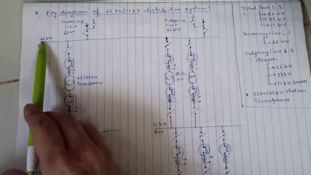
A single line diagram of a substation can be drawn by starting with a basic outline of the equipment. The next step is to add in the power lines and other connections. Finally, all of the labeling should be added to identify the various components.
EE-303 lecture 16: Single Line Diagram of 33kv/11kv sub station/BTER/How to draw /electrical study
- Identify all the substation equipment
- Draw a rectangle around each piece of equipment
- Connect the rectangles with single lines to indicate the electrical connectivity of the equipment
- Label each piece of equipment with its name and voltage rating
Single Line Diagram of Panel Board
A panel board is a device that distributes electrical power to multiple circuits. It is typically used in residential and commercial applications. A panel board usually has a main breaker or switch that controls the flow of electricity to the various circuits.
The panel board also has individual circuit breakers or fuses that protect each circuit from overloading.
Single Line Diagram of Power Distribution
A single line diagram of a power distribution system is a simplified representation of the physical components and circuits that make up the system. It is typically used by engineers and electricians to understand how the system works and to troubleshoot problems. The single line diagram shows the main components of the system, including the transformer, switchgear, circuit breakers, and busbars.
It also shows the path of the electrical current through the system.

Credit: electrical-engineering-portal.com
How Do You Draw a Single-Line Diagram in Power System?
A single line diagram in a power system is a representation of that system using abstract, graphic symbols to represent the components of the system. The purpose of a single line diagram is to show the relationship between the different parts of the system, and how they are interconnected.
Single line diagrams are typically used in electrical engineering, and they can be created for any type of electrical system.
There are many different software programs that can be used to create a single line diagram, or SLD.
The first step in creating an SLD is to identify all of the components that will be included in the diagram. Once all of the components have been identified, they can be added to the SLD by placing them on the canvas and connecting them together with lines.
The lines on an SLD represent either physical connections between devices, or logical connections between circuits.
After all of the components have been added to the SLD and connected together, labels can be added to each component to identify its function. Finally, any additional information that may be relevant to understanding the power system can be added to the SLD as well.
How Do You Study a Single-Line Diagram of Substation?
Substation single line diagrams can be studied by looking at the individual components and their connections to one another. The first step is to identify all of the major components, such as transformers, breakers, and busbars. Then, trace the connections between these components to see how they are interconnected.
Finally, examine how power flows through the substation by tracing the path of the conductor from its source to its destination. By understanding how each component works and how it is connected to other parts of the substation, you can gain a clear picture of how the entire system operates.
How Do I Create a Substation Layout?
Assuming you want to know how to lay out a substation in AutoCAD, here are the basic steps:
1. Decide on the size of your substation. This will determine the number of bays and equipment you can include.
2. Create a basic layout of the substation, including bays for each piece of equipment.
3. Add details like switchgear, transformers, cabling, and other necessary components.
4. Make sure everything is to scale and correctly positioned according to your design specifications.
5. Once you’re satisfied with the layout, save it as a template for future use.
What Information is in a Single-Line Diagram of Substation?
A typical single-line diagram of a substation will show the following:
-The equipment within the substation including breakers, transformers, and other devices.
-The voltage levels within the substation.
-The primary and secondary connections between these pieces of equipment.
-Identification tags for each piece of equipment.
Conclusion
A single line diagram of a substation shows the equipment and connections in a simplified way that makes it easy to understand the operation of the substation. The diagram includes all of the major components of the substation, such as transformers, switches, circuit breakers, and busbars. The diagram also shows how these components are connected to each other.


