A 66Kv substation key diagram is a specialized type of electrical engineering drawing that shows the detailed connections and layouts of the equipment in a 66Kv substation. It usually includes a one-line diagram, which is a simplified representation of the substation equipment and how it is interconnected, as well as more detailed schematics of individual pieces of equipment. The key diagram is an essential tool for planning, constructing, and maintaining a 66Kv substation.
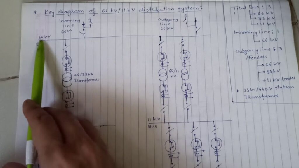
Part 4 one line key diagram of a typical 66kV / 11kV Distribution Substation
If you’re looking for a key diagram of a 66Kv substation, you’ve come to the right place. This substation is responsible for providing power to homes and businesses in the area, and it’s absolutely critical that it stays up and running. In this blog post, we’ll take a look at the key components of this substation and how they all work together.
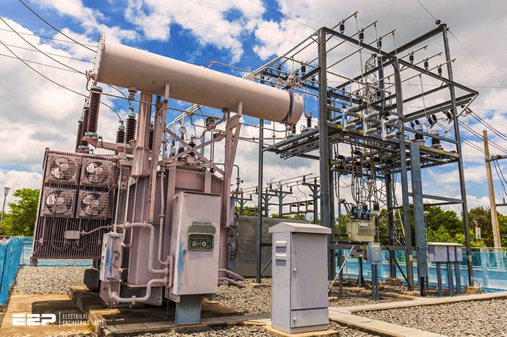
The first thing you’ll notice on the key diagram is the transformer. This piece of equipment takes incoming high-voltage power from the utility company and steps it down to a lower voltage that can be used by homes and businesses. The transformer is absolutely critical to the operation of the substation, so it’s important that it is well-maintained.
Next, you’ll see several large circuit breakers. These breakers are used to protect equipment in the substation from overloads or faults in the electrical system. If there is an issue with one of these breakers, it can cause major problems for the entire substation.
That’s why it’s so important that they are regularly inspected and maintained.
Finally, you’ll see several cables running into and out of the substation. These cables carry electricity from the transformer to different parts of town or to other substations.
They also carry electricity back to the utility company when people in town use more power than what is being generated at the substation.
That’s a quick overview of some of the key components in a 66Kv substation. It’s important to understand how these pieces work together because they play such a vital role in keeping our power grid running smoothly.
66Kv Substation Pdf
If you are in the process of designing or expanding a 66kv substation, there are a few things that you need to take into account. In this blog post, we will go over some of the key considerations for your 66kv substation design.
First, you need to decide on the voltage and current levels that your substation will be able to handle.
This will determine the size and type of transformers and other equipment that you will need. You also need to consider the layout of your substation, as well as the environmental conditions that it will be operating in.
Once you have all of these factors sorted out, you can start looking at the different types of 66kv substations.
There are two main types: air-insulated and gas-insulated. Air-insulated substations are less expensive and easier to maintain, but they are not as efficient as gas-insulated ones. Gas-insulated substations are more expensive to build and operate, but they offer better performance and reliability.
Finally, you need to choose a site for your 66kv substation. The site should be large enough to accommodate all of the equipment needed for your chosen voltage and current levels. It should also be close to existing power lines so that connecting your new substation is easy and cost-effective.
66 Kv Substation Components
A 66 kV substation is a critical part of the electrical grid, providing power to homes and businesses. The substation includes several key components, each of which plays an important role in keeping the power flowing.
The first component is the transformer, which steps down the voltage from the high-voltage transmission lines to a level that can be used by homes and businesses.
The transformer is a large, expensive piece of equipment, and it must be carefully maintained to ensure that it continues to operate safely and efficiently.
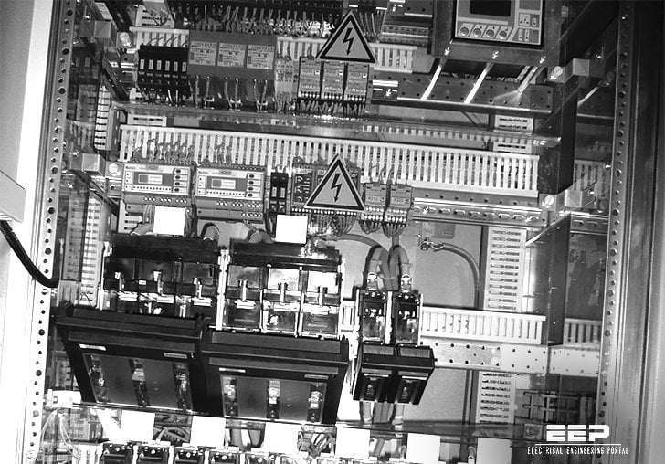
The second key component is the switchgear, which controls the flow of electricity through the substation. The switchgear includes circuit breakers, switches, and other devices that allow operators to safely control the flow of electricity.
The third key component is the grounding system, which helps protect against electrocution and damage to equipment. The grounding system includes copper rods or plates buried in the ground, as well as bonding wire connecting all of the metallic parts of the substation.
Finally, the fourth key component is security fencing and gateways, which help protect people and animals from coming into contact with live electrical equipment.
Fencing should be tall enough to deter climbers, and gates should be equipped with warning signs and alarms.

Credit: sub-stn-lalton.blogspot.com
What is 66Kv Substation?
A 66 kV substation is a type of electrical substation that uses voltages in the range of 60-66 kV. These substations are used to supply electricity to medium and high voltage loads such as industrial plants, distribution networks, and transmission lines. The main components of a 66 kV substation include transformers, switchgear, circuit breakers, and power line carrier equipment.
What is the Diagram Needed is a Substation?
As someone who works in the electrical engineering field, I am often asked about substations and what exactly they are. A substation is a crucial part of the power grid, as it is responsible for changing the voltage of electricity so that it can be safely transported over long distances. Substations can be found all over the world, and range in size from small to very large.
There are a few different types of substations, but the most common one is the transmission substation. These substations take high-voltage electricity from power plants and transform it into lower voltages so that it can be sent through power lines to homes and businesses. Substations also play an important role in keeping the power grid stable by regulating supply and demand.
While transmission substations are the most common type, there are also other types of substations such as distribution substations and generation substations. Distribution substations take electricity from transmission lines and lower the voltage even further so that it can be sent to houses or buildings through smaller wires. Generation substations are typically located at power plants where electricity is first produced.
No matter what type of substation it is, they all have one thing in common: They contain a variety of devices and equipment that work together to change the voltage of electricity so that it can be used safely throughout our homes and businesses.
What are the Three Main Parts of a Substation?
A substation is a critical part of the electrical grid. It is a junction point where high-voltage transmission lines meet lower-voltage distribution lines or where electricity is generated and then transformed for use on the grid. Substation equipment includes transformers, circuit breakers, and other equipment necessary to control the flow of electricity.
The three main parts of a substation are:
1) The high-voltage switchyard – This is where the high-voltage transmission lines terminate. The switchgear in this area controls the flow of electricity from these lines.
2) The low-voltage switchyard – This area contains the transformers that lower the voltage of the electricity for distribution to homes and businesses. The switchgear here controls the flow of electricity to and from these transformers.
3) The control building – This houses the equipment needed to monitor and control the substation equipment.
This may include computers, telecommunication equipment, and other electronic devices.
How to Read Substation Single-Line Diagram?
Substation single-line diagrams show the primary and secondary electrical equipment within a substation, as well as the path that electricity takes through the substation. The single-line diagram is a powerful tool that allows substation personnel to understand the relationships between equipment and how electricity flows through the substation.
To read a substation single-line diagram, one must first understand the symbols used on the diagram.
The most common symbols are:
• Busbar – this is represented by a thick horizontal or vertical line, sometimes with arrowheads indicating direction of flow
• Switchgear – this is represented by two parallel lines with a gap between them, sometimes with an X or triangle in the middle
• Transformers – this is represented by two overlapping circles connected by a zigzag line
• Capacitors – this is represented by two overlapping circles connected by a straight line
After understanding the symbols used on the diagram, one can then begin to trace the path of electricity through the substation.
Begin at either end of the busbar and follow it until you reach a switchgear. Then, continue followingthe path of electricity until you reach another piece of equipment. Repeat this process until you have tracedthe path of electricity through every piece of equipment in the substation.
Conclusion
A 66kv substation is a key component in the distribution of electricity. It is responsible for stepping down the voltage from the high-voltage transmission lines to a level that can be used by customers. The substation also contains various devices that protect and control the flow of electricity.


