A schematic diagram of a substation is a drawing that shows the layout of the equipment and how it is connected. It typically includes the transformer, switchgear, circuit breakers, and other equipment.
Single line diagram of substations
A substation is an important part of the electrical grid. It is a collection of equipment that transforms electricity from one voltage to another. This enables the electricity to be sent over long distances without losing its strength.
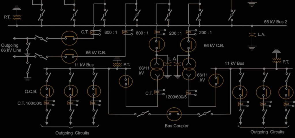
A schematic diagram of a substation is shown below.
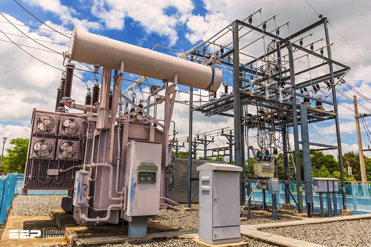
The first piece of equipment in a substation is the transformer. The transformer changes the voltage of the electricity so that it can be sent across long distances without losing its strength.
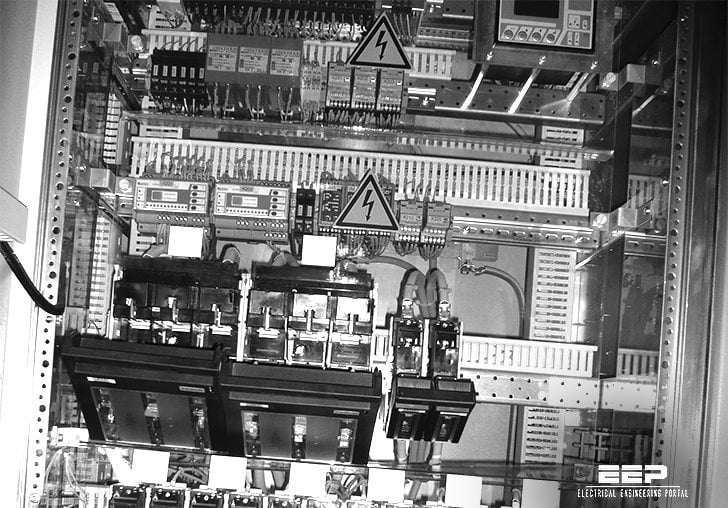
The next piece of equipment is the switchgear. The switchgear controls the flow of electricity and protects the transformer from overloads. The last piece of equipment in a substation is the capacitor bank.
The capacitor bank helps to regulate the voltage and keep it at a constant level.
66 Kv Substation Components
A 66 Kv Substation is a medium voltage power substation. It steps down the voltage from the transmission line to a level that can be used by the distribution system. The components of a 66 Kv substation include:
-Transformers: to step down the voltage
-Circuit breakers: to disconnect equipment when necessary
-Capacitors: to improve power factor
-Bus bars: to connect equipment together
-Grounding rods: for safety
-Isolators: to isolate equipment when necessary
A typical 66/11 kV substation layout is shown in Figure 1. The main components are transformers, circuit breakers, busbars and Earthing (grounding) devices. Additional minor items are also present such as capacitors, control panels, meters etc., but these will not be considered further here.

Credit: 3phaseassociates.com
What is a Substation Diagram?
A substation diagram is a drawing that shows the equipment and connections in a substation. It is used to plan the layout of the substation and to understand how the equipment works together.
What are the Three Main Parts of a Substation?
A substation is a critical part of the electrical grid. It is where high-voltage electricity from power plants is transformed into the lower voltages used in homes and businesses. A substation has three main components: transformers, switchgear, and controls.
The transformer is the heart of the substation, converting high-voltage electricity to a lower voltage. The switchgear controls the flow of electricity through the substation, and the controls monitor and protect equipment from damage caused by faults or surges in voltage.
How Does a Substation System Work?
A substation is a power system facility that is used to switch, regulate and transform electricity. A substation can be as simple as a single transformer connected to a medium voltage distribution line or it can be a complex multi-unit installation with high voltage switchgear, busbars, circuit breakers, transformers and other equipment. The primary function of a substation is to receive electricity from the transmission system and distribute it to consumers via the distribution system.
Substations are usually located at points along the electric power grid where electricity needs to be either generated or transmitted. Substations may also be located near large industrial facilities or load centers that require electrical power. In addition, some substations are built specifically for emergency backup purposes in case of power outages.
A typical substation includes one or more high voltage busbars that collect electricity from incoming transmission lines and distribute it to outgoing feeder lines. High voltage circuit breakers are used to isolate sections of the substation for maintenance purposes. Low voltage switchgear is used to control the distribution of electricity within the substation itself.
Transformers are used to step down the high voltages coming into the substation so that they can be safely distributed to consumers via lower voltage distribution lines.
How to Read a Substation One-Line Diagram?
Substation one-line diagrams are an important tool for understanding the electrical distribution system. The one-line diagram is a simplified representation of the substation that shows the main components and their interconnections. One-line diagrams are typically drawn with relays, switches, and other devices represented by symbols.
The one-line diagram can be used to determine the location of equipment and to understand the operation of the substation.
Conclusion
A substation is a crucial part of the electrical grid, and its schematic diagram can be very helpful in understanding how it works. This blog post provides an overview of the different parts of a substation and how they fit together. It also includes a detailed explanation of what each component does and how it contributes to the overall operation of the substation.


