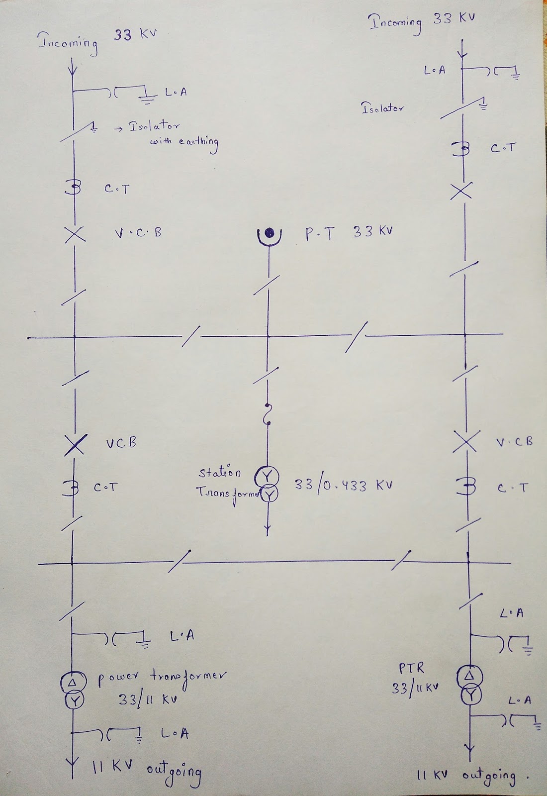
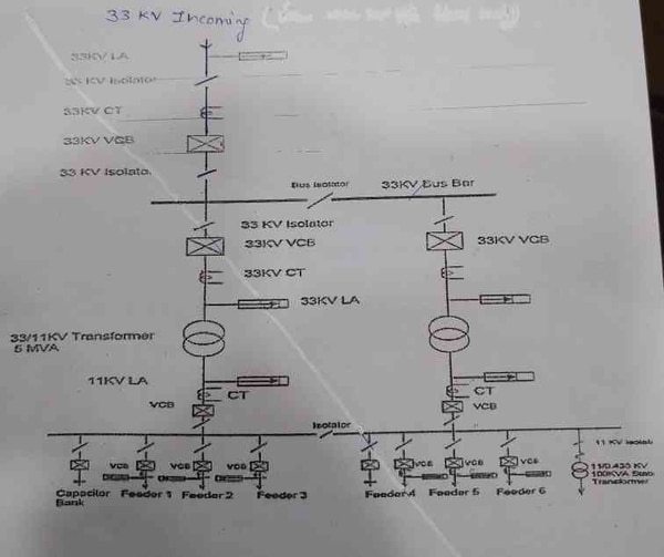
A single line diagram is a simplified way to represent a three-phase power system. The diagram shows the main components of the 33/11 kV substation including transformers, switchgear, and protection devices.
SINGLE LINE DIAGRAM 33KV/11KV SUBSTATION in hindi
A single line diagram (SLD) is an important electrical engineering document that shows how power system equipment is connected. The 33/11 substation SLD provides a high-level overview of the equipment and connections at this critical facility. This includes both primary and secondary equipment, as well as associated protection devices.
The SLD also identifies key performance indicators for the substation, such as voltage and current levels. By understanding this information, engineers can effectively manage power flow and ensure the stability of the electric grid.

Credit: rotricksyoutube.blogspot.com
How to Read Single Line Diagram of Substation?
In order to understand how to read a single line diagram of a substation, it is important to first understand what a single line diagram is. A single line diagram is a drawing that shows the electrical components of the substation and how they are connected. The purpose of the single line diagram is to provide a clear and concise picture of the substation’s electrical configuration.
The first step in reading a single line diagram is to identify the different symbols that are used. Each symbol represents a different component of the substation, such as transformers, breakers, or buses. Once all of the symbols have been identified, it is then possible to trace the path of electricity through the substation.
This will help to identify any potential problems that may exist within the system.
It is important to note that not all single line diagrams will be laid out in the same way. However, most diagrams will follow a similar format that includes three main sections: power supply, switchgear, and distribution equipment.
By understanding how to read this type of diagram, it will be possible to quickly and easily identify any issues that may exist within a substation’s electrical system.
What is Single Line Diagram of Substation?
A single line diagram (SLD) is a specialized type of schematic drawing that uses single lines and symbols to represent the components in an electrical substation. The single line diagram is the most basic type of electrical power system drawing. It shows the major components of the substation and how they are interconnected.
The single line diagram does not show the detailed information about the individual components, but it does show their general arrangement and relationship to each other. The main purpose of the single line diagram is to provide a quick and easy way to visualize the electrical power system.
The single line diagram can be divided into two main parts:
– The left side contains all of the primary equipment such as transformers, circuit breakers, and buses.
– The right side contains all of the secondary equipment such as switchgear, relays, meters, and controls.
Each side of the diagram has its own set of symbols that represent different types of equipment.
For example, on the left side transformer symbols will be shown while on the right side relay symbols will be shown.
Generally speaking, primary equipment is connected together with solid lines while secondary equipment is connected together with dashed lines. This distinction helps to quickly identify which pieces of equipment are directly linked together electrically.
What is 33 11 Kv Transmission Line?
The 33 11 kV transmission line is a high voltage power line that transmits electricity from the 33 kV substation to the 11 kV substation. The line consists of two conductors, each carrying an alternating current (AC) of 33,000 volts. The conductors are supported by lattice towers or pylons, and are insulated from each other and from the ground.
The 33 11 kV transmission line is used to transport electrical energy over long distances. It is one of the most efficient ways to transmit electricity, and can be used for both AC and DC power. The line is capable of carrying a large amount of electrical current, making it ideal for use in high-voltage applications such as power plants and industrial facilities.
What is 33 11 Kv Substation?
A 33 11 kV substation is a type of electrical substation that uses 33,000 volts (33 kV) of alternating current (AC) to supply electricity to 11,000 volt (11 kV) AC electrical grids. This type of substation is typically used in countries where the electric grid voltage is relatively low, such as in Europe and Japan. A 33 11 kV substation can also be used to connect two different types of electrical grids together, such as connecting a European grid to a Japanese one.
Conclusion
The blog post explains the single line diagram of a 33/11 kV substation. It shows how the different components are connected and how they work together. The post also includes a brief explanation of each component.


