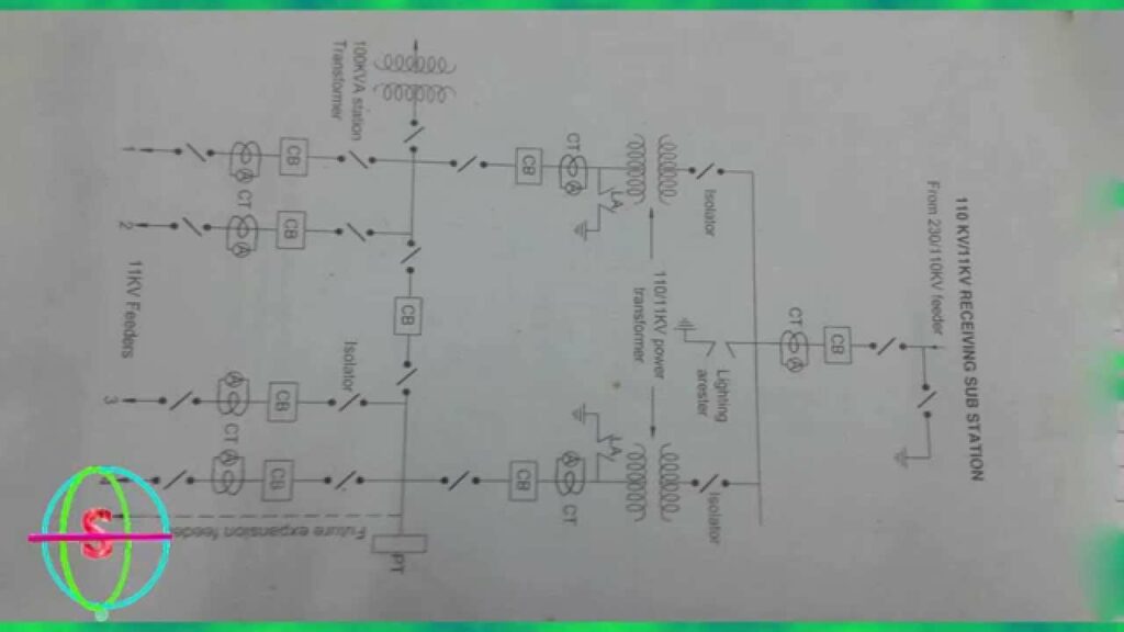
A single line diagram of a substation feeder is a simplified representation of the physical and electrical components of the substation. It is typically used for planning and operational purposes. The single line diagram includes all switchgear, equipment, circuits, and conductors in the substation, as well as their respective ratings and clearances.
SINGLE LINE DIAGRAM 33KV/11KV SUBSTATION in hindi
A single line diagram of a substation feeder is a simplified representation of the electrical equipment and connections within the substation. It shows the main components of the substation, their relative positions, and how they are interconnected. The single line diagram is an important tool for planning and designing substations.

Credit: www.alamy.com
How Do You Read a Substation on a Single Line Diagram?
In order to read a substation on a single line diagram, you will need to familiarize yourself with the different symbols that are used. Once you have done this, you will be able to identify the different components of the substation and understand how they are interconnected. The following is a step-by-step guide on how to read a substation on a single line diagram:
1) Familiarize yourself with the different symbols that are used. Each symbol represents a different component of the substation.
2) Identify the power source for the substation.
This is typically represented by a large circle with arrows pointing inwards.
3) Trace the path of electricity from the power source through each component of the substation until it reaches its destination. This will help you understand how each component works together to provide power to the final destination.
What is a Feeder in a Substation?
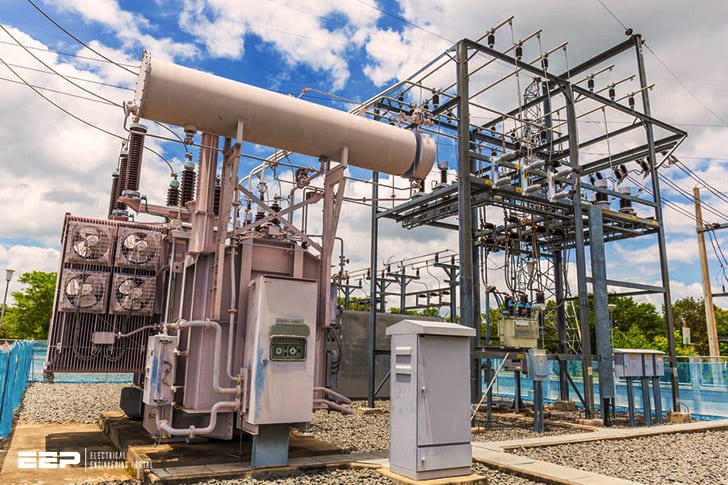
A substation is an electrical installation where voltage is transformed from high to low, or the reverse, using transformers. A feeder supplies power to the substation transformer coils from the utility’s distribution grid. The primary winding of the transformer is connected to the high-voltage side of the feeder, while the secondary winding is connected to the low-voltage side.
How Many Feeders are in a Substation?
The number of feeders in a substation can vary depending on the size and capacity of the substation. A small substation may have only two or three feeders, while a large substation could have dozens. The feeders are responsible for bringing electricity into the substation from the power grid and distributing it to the various transformers within the substation.
What is the Difference between Feeder And Busbar?
A busbar is an electrical conductor that carries high current and voltage. It is used to connect two or more electrical devices together. A feeder is an electrical device that supplies power to an electrical system.
Conclusion
In a single line diagram of a substation, the feeders are shown as single lines coming from the utility transformer and going to the main bus. The main bus is then connected to the secondary bus, which is connected to the loads.


