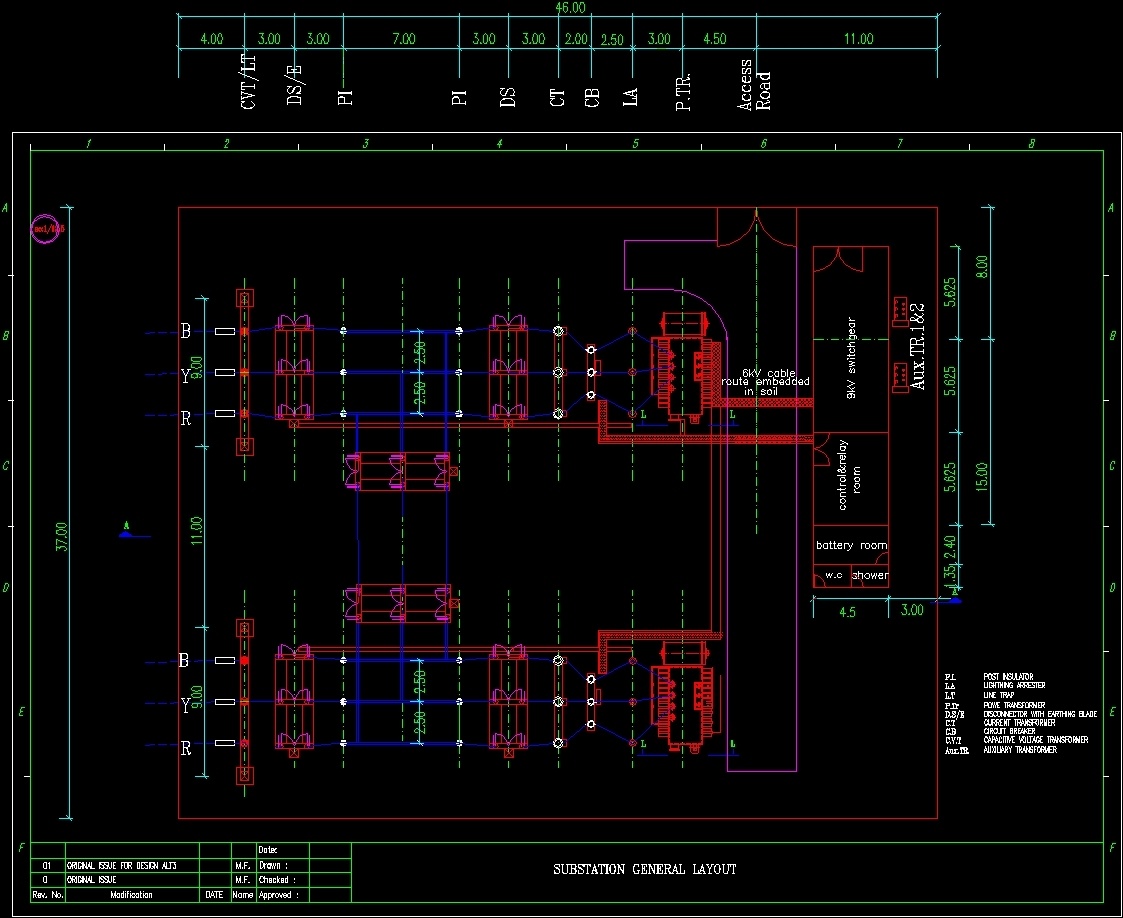
A single line diagram (SLD) is a type of electrical drawing that shows the connections between the main components in a substation. It is the most common type of drawing used by electrical engineers and is typically used to show the layout of a substation, as well as the locations of circuit breakers, transformers, and other equipment.
Single Line Diagram of 11kV Substation in AutoCAD Electrical
Do you need to create a single line diagram of a substation in Autocad? If so, this blog post is for you! We will walk you through the steps needed to create a accurate and professional looking single line diagram.
First, you will need to gather all of the necessary information. This includes the dimensions of the substation, the equipment locations, and any other relevant data. Once you have this information, you can begin creating your drawing in Autocad.
The first step is to draw the outline of the substation. Be sure to include all of the relevant details such as doors, windows, and stairs. Next, add in the equipment locations.
You can use symbols to represent each piece of equipment. Finally, add in any connecting lines between pieces of equipment. These lines represent electrical circuits or other connections between pieces of equipment.
Once you have completed your drawing, it is important to check it for accuracy. Make sure all dimensions are correct and that everything is properly connected. Once you are satisfied with your drawing, save it and print it out for future reference!
Single Line Diagram, Autocad File Download
Single Line Diagram, Autocad File Download
Description:
Download this FREE 2D CAD Block of a SINGLE LINE DIAGRAM.
This AutoCAD drawing can be used in your electrical design CAD drawings. (AutoCAD 2004.dwg format) Our CAD drawings are purged to keep the files clean of any unwanted layers.
How to Draw Electrical Single Line Diagram in Autocad Pdf
In this blog post, we will be discussing how to single line diagram in Autocad pdf. This is a great skill to know for any engineer or designer as it can be used to create quick and easy designs. We will also be providing a few tips and tricks on how to make your designs look more professional.
Let’s get started!
The first thing you need to do when creating a single line diagram in Autocad pdf is to draw your electrical components. You can do this by using the various shapes and tools that Autocad has to offer.
Once you have all of your components drawn out, you need to connect them together with lines. These lines represent the different electrical connections between your components.
Once you have all of your lines drawn, you need to add labels to each one.
These labels should include the name of the component, the voltage, and the current flowing through it. Adding these labels will help you keep track of your design and make sure that everything is connected correctly.
Now that you have all of your electrical components drawn and labeled, you are ready to start wiring them together.
To do this, you will need to use the “Wiring” tool in Autocad pdf. This tool allows you to quickly connect two points together with a line. Simply click on one point, then click on another point that you want to wire together, and finally click on the “Wiring” tool again.
Repeat this process until all of your components are wired together.
Finally, once all of your wiring is complete, you can add text annotations anywhere needed throughout your design using the “Text” tool in Autocad pdf . These annotations can be used for things like adding warnings or notes about specific areas of your design.
That’s it! You now know how draw electrical single line diagrams in Autocad pdf .

Credit: designscad.com
How Do I Make a Single Line Diagram in Autocad?
When it comes to electrical engineering, a single line diagram (SLD) is a very useful tool. SLDs show the connectivity of circuits in a concise and easy-to-understand format. And when it comes to creating one, AutoCAD is a great software option.
In this blog post, we’ll go over how to make a SLD in AutoCAD step-by-step.
First things first, you’ll need to open up AutoCAD and start a new drawing. Then, go to the “Insert” tab on the ribbon and click “Block.”
In the “Name” field, type in “.SLDBLK.” This will insert the SLD block into your drawing.
Now it’s time to start adding your symbols.
The most common symbols used in an SLD are:
– Lines (for conductors)
– Circles (for breakers or fuses)
– Triangles (for transformers)
– Squares (for motors or generators)
To add a symbol, simply click on the corresponding icon in the “Symbol” palette and then click wherever you want to place it in your drawing.
You can also use the “Mirror” tool to create duplicate symbols.
Once you have all of your symbols placed, it’s time to start connecting them with lines. To do this, select the “Line” tool and then click on two different symbols that you want to connect.
A line will automatically be drawn between them. Repeat this process until all of your symbols are connected.
You can also add labels to your lines by clicking on them and then typing in whatever text you want under the “Text” tab on the ribbon bar.
And that’s all there is to it! Creating an SLD in AutoCAD is actually pretty simple once you get the hang of it.
What is Single Line Diagram of Substation?
In engineering, a single line diagram (SLD) is a type of simplified drawing that uses a single line to represent three-phase electrical system. It is the most basic type of substation layout. The single line diagram is the blueprint for reconfiguring an existing substation or building a new one.
From the single line diagram, all primary equipment such as transformers, circuit breakers and disconnects can be seen along with their associated ratings and identified by nameplate information.
How Do You Draw an Electrical Single Line Diagram?
In order to draw an electrical single line diagram, you will need to start with a basic understanding of how the electrical system in your home or office works. Once you have this knowledge, you can then begin to draw the diagram. The most important thing to keep in mind when drawing an electrical single line diagram is that all lines must be drawn in a continuous path.
This means that you cannot have any gaps or breaks in the lines. Each line on the diagram represents a different circuit within the electrical system. In order to properly label each line, you will need to know the various components of the system and their respective locations.
How Do You Draw an Electrical Wiring Diagram in Autocad?
When it comes to drawing an electrical wiring diagram in AutoCAD, there are a few things that you will need to keep in mind. First of all, you will need to make sure that all of the symbols that you use are accurate. This means that you will need to find the right symbol for each component that you are using.
You can find these symbols by searching online or by looking in the AutoCAD help files.
Once you have all of the symbols that you need, you will then need to draw out the actual wiring diagram. To do this, you will first need to determine where all of the components will go.
Once you have done this, you can then start connecting them together with lines. Make sure that each line is drawn very carefully so that it is easy to follow later on.
Once you have your diagram complete, it is important to test it out before saving it.
This can be done by running a simulation in AutoCAD or by printing it out and testing it yourself. By doing this, you can catch any mistakes that you may have made and correct them before they become a problem later on down the road.
Conclusion
A single line diagram of a substation in Autocad is a drawing that shows the location of all the components of the substation, as well as their relationship to each other. It is an important tool for engineers when designing or troubleshooting a substation.


