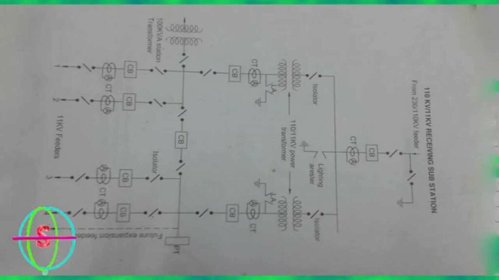
A single line diagram of a substation is a drawing that shows the electrical equipment and connections in a simplified way. It is usually used for planning and design purposes.
Single line diagram of substations
A single line diagram of a substation is a drawing that shows the layout of the equipment and how it is interconnected. It can be used to help determine what equipment is needed for a particular application and how it should be connected.

Credit: electrical-engineering-portal.com
What is Single-Line Diagram of Substation?
A single line diagram of a substation shows the equipment and connections between the various parts of the substation. This includes the primary voltage source, secondary voltage sources, transformers, switchgear, circuit breakers, and other equipment. The single line diagram also shows how these components are interconnected.
How to Read Substation Single-Line Diagram?
If you work in the electrical power industry, it’s likely that you’ll need to be able to read a substation single line diagram. While they may look confusing at first, single line diagrams provide a clear and concise way to represent the electrical equipment and circuits in a substation. In this blog post, we’ll walk through how to read a substation single line diagram.
A substation single line diagram will typically show three things:
– The major components of the substation
– The connections between those components
– The voltage levels present in the substation
Let’s take a look at each of these in turn.
The first thing you’ll notice on a substation single line diagram are the various symbols that represent the different pieces of equipment.
These includetransformers, circuit breakers, buses, capacitors, and more. Each symbol is intended to give you a quick way to identify the type of component it represents.
In addition to showing the individual components, a substation single line diagram will also show how those components are interconnected.
This is represented by lines between the various symbols. The thickness of these lines corresponds to the size (or amperage rating) of conductor used for that particular circuit. Finally, you’ll also see voltage levels indicated on some or all of the equipment symbols.
This is important information as it tells you what kind of devices can be connected together without risking damage due to mismatched voltages.
Now that we’ve looked at what information is shown on a typical substation single line diagram, let’s talk about how to actually interpret and use this information. One common way to approach reading such a drawing is known as “followingthe flow.”
This simply means starting at one point on the drawing and then tracing your finger along each successive connection until you reach your final destination point. Doing this allows you visualize how electricity flows throughthe various pieces of equipment in the substation – which can be helpful when tryingtroubleshoot problems or understand system interactions better.. Another helpful tip when reading Substationsingleline diagrams issimply taking noteof any changesin voltage levelthat occuralongthe way.. Thiswill helpyou keep trackof potential”bottlenecks”in theelectrical system where lower voltage devices must connectto highervoltagecircuits.. By understanding bothhowto reada Substationsingle linediagramas well aswhatinformationit contains,.
How Do You Make a Sld Diagram?
In order to make a SLD diagram, you will need to first understand what a SLD is and how it functions. A SLD, or systematic layout design, is a type of diagrams that helps visualize the flow of work within a facility. It is typically used in manufacturing and industrial settings in order to optimize the use of space and improve efficiency.
There are three main types of SLDs: process-oriented, product-oriented, and hybrid. Process-oriented SLDs focus on the movement of materials and workers throughout the facility, while product-oriented SLDs emphasize the storage and retrieval of products. Hybrid SLDs combine both approaches.
Once you have decided which type of SLD is best suited for your needs, you will need to gather accurate information about your facility. This includes measurements of all spaces, as well as data on workflow patterns, material handling methods, and employee movements. With this information in hand, you can begin creating your diagram.
There are several software programs available that can help with this process (such as AutoCAD or SmartDraw), or you can create your own diagram using graph paper or a blank sheet of paper. When creating your diagram, be sure to use symbols to represent different areas (storage shelves, offices, restrooms) and arrows to show the flow of traffic and materials. You may also want to add annotations explaining specific details or processes.
Once your diagram is complete, take some time to review it and make sure that it accurately reflects reality. Then put it into action! Use your new knowledge of the layout of your facility to streamline processes and improve efficiency.
How Do I Create a Substation Layout?
Assuming you want to know how to lay out a typical substation:
A substation layout generally includes the following features:
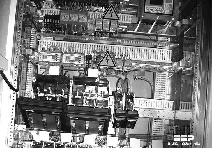
-The control house, which contains the equipment used to control and monitor the substation
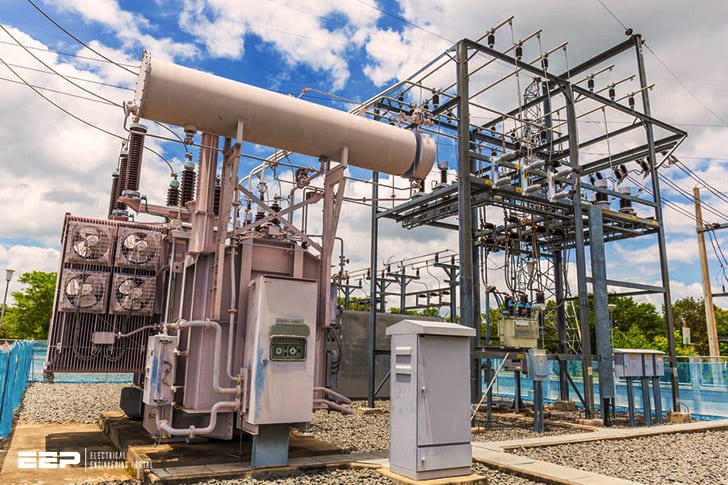
-The transformer yard, which houses the transformers that step down or up the voltage levels
-The switchgear, which consists of the high voltage switches that control the flow of electricity
-The busbars, which are metal bars used to conduct electricity within the substation
-Cables and conductors, which carry electricity from one part of the substation to another
Conclusion
A single line diagram of a substation pdf is a great way to get an overview of the substation. It shows all the components in the substation and how they are interconnected.


