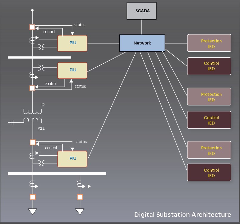
A substation block diagram is a graphical representation of a power system that includes the major components of a substation. The diagram shows the location of each component and how they are interconnected.
A substation block diagram is a graphical representation of a power system, typically used by engineers. It shows the different components of the system and how they are interconnected. The diagram can be used to understand the system’s design and operation, and to troubleshoot problems.
66 Kv Substation Components
A 66 kV substation is a high-voltage electrical substation that transforms and switches electrical energy at voltages above 60 kV. A typical 66 kV substation consists of several components, including transformers, circuit breakers, switchgear, and more.
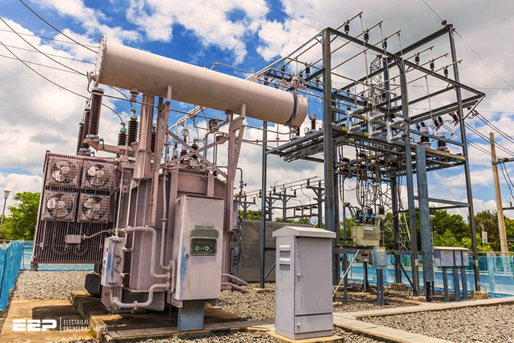
The most important component in a 66 kV substation is the transformer.
The transformer increases or decreases the voltage of electricity passing through it, depending on the needs of the system. Transformers can be either air-cooled or oil-cooled, and are typically located outdoors.
Circuit breakers are another critical component in a 66 kV substation.
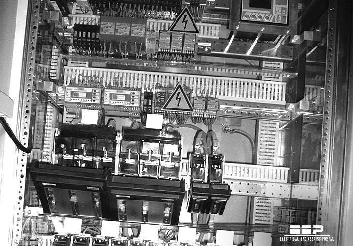
Circuit breakers protect equipment from damage by automatically disconnecting circuits when they become overloaded. Switchgear is used to control the flow of electricity within the substation, and may include devices such as fuses and relays.

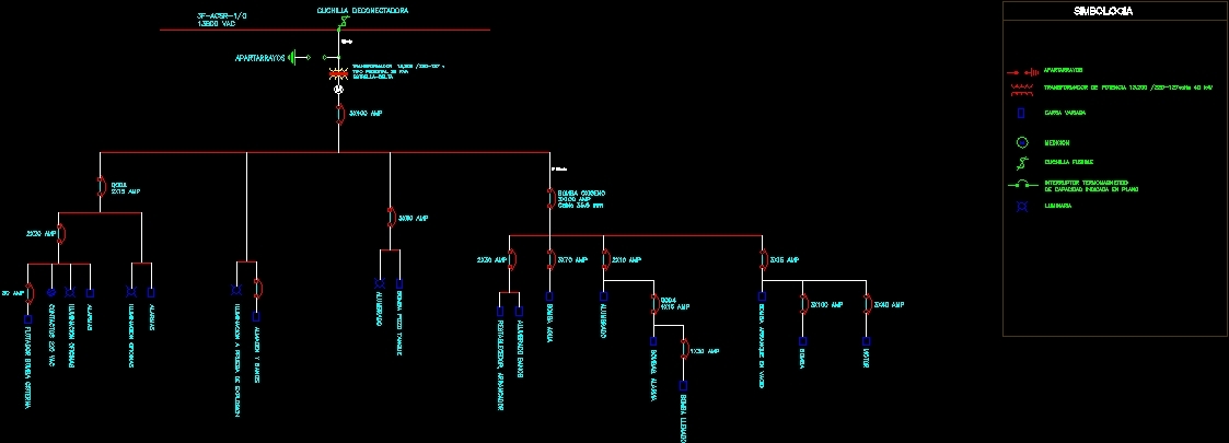
Credit: designscad.com
What is a Substation Diagram?
A substation diagram is a drawing that shows the layout of equipment within a substation. It includes the location of each piece of equipment, its function, and how it is interconnected with other equipment. The diagram may also show the location of power lines, transformers, and other devices that are not part of the substation itself.
What are the Three Main Parts of a Substation?
A substation is a critical part of the electrical grid. It is where high-voltage electricity from power plants is transformed into lower voltages for distribution to homes and businesses. Without substations, the electricity we use every day would not be possible.
Substations come in all shapes and sizes, but they all have three key components: transformers, circuit breakers, and busbars. Let’s take a closer look at each of these important parts.
Transformers are used to change the voltage of electricity.
A transformer consists of two coils of wire wrapped around a metal core. When electricity flows through the first coil (the primary winding), it creates a magnetic field in the core. This magnetic field then induces a current in the second coil (the secondary winding).
By changing the number of turns in each coil, transformers can either increase or decrease voltage.
Circuit breakers are devices that protect transformers (and other equipment) from damage caused by excessive currents flowing through them. When too much current flows through a circuit breaker, it trips and opens up, interrupting the flow of electricity and preventing damage to equipment.
Busbars are thick copper or aluminum bars that conduct electricity between circuit breakers, transformers, and other equipment within a substation. Busbars typically have a high amperage rating so that they can carry large amounts of current without overheating.
What is a Substation And How Does It Work?
A substation is a crucial part of the electric power grid. It is a collection of electrical equipment that transforms high-voltage transmission line voltage to a lower voltage that can be used by consumers. A substation also provides switching, protection, and sometimes storage for electricity.
The first step in understanding how a substation works is to understand the difference between voltages. Transmission lines carry electricity at very high voltages (usually 115,000 volts or more). The higher the voltage, the less current is needed to transmit power over long distances.
This means that fewer wires are needed, which reduces costs and improves efficiency.
However, this high voltage cannot be used by most appliances and devices in our homes, which operate at much lower voltages (typically 110 volts). Therefore, substations are necessary to reduce the transmission line voltage to a level that can be used safely and efficiently by consumers.
Substations usually consist of three main components: transformers, circuit breakers, and switches.
Transformers are devices that change the voltage of an electric current without changing its frequency. In other words, they increase or decrease the amount of electricity flowing through a wire without affecting how often the electrons flow past a given point per second.
Circuit breakers are special switches designed to protect electrical equipment from damage caused by overloads or short circuits. When too much current flows through circuit breaker contacts, they open (or “trip”) to interrupt the circuit and prevent further damage.
Switches are devices that complete or interrupt an electrical circuit under normal conditions as well as during faults such as short circuits or ground faults.
How Do I Create a Substation Layout?
When creating a substation layout, there are many factors to consider. The first is the equipment that will be housed in the substation. This includes transformers, switchgear, breakers, and other electrical equipment.
The layout of the substation must accommodate this equipment and allow for proper maintenance and operation. Another important factor is the voltage of the system. The substation must be designed to handle the voltages present on the system.
This includes both the primary and secondary voltages. Finally, the layout must also take into account any safety concerns. The substation must be designed so that workers can safely access all areas of the facility.
Single line diagram of substations
Conclusion
As you can see from the substation block diagram, the main components of a substation are the transformers, switchgear, and relays. The power flow through a substation is as follows: first, the transformer steps down the voltage from the transmission line to a level that can be used by the distribution system. Next, the switchgear controls the flow of electricity to and from the transformer.
Finally, relays are used to protect the transformer and other equipment in the substation from damage due to faults on the electrical grid.


