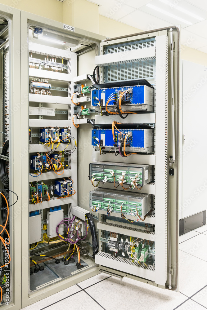
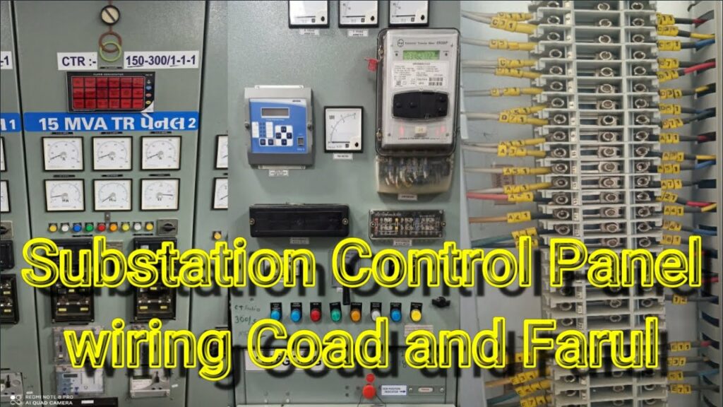
A control panel is used in a substation to monitor and control the electrical equipment. The panel typically contains switches, gauges, and other devices that allow an operator to control the equipment.
If you’re in the electrical industry, then you know that a substation control panel is vital to the operation of any substation. But what do you need to know about wiring a substation control panel? Let’s take a look.
First, it’s important to understand the basics of a substation control panel. A typical substation control panel will have two parts: the main breaker and the feeder breakers. The main breaker is responsible for controlling the flow of electricity into the substation, while the feeder breakers distribute power to different parts of the substation.
In order to wire a substation control panel, you’ll need to use specialised cable. This cable is designed to handle high voltage and current, and it must be installed correctly in order to avoid damage or injury. Once your cables are in place, you’ll need to connect them to the appropriate terminals on the control panel.
It’s important to get this right, as an incorrect connection could result in serious problems.
Once everything is wired up, it’s time to test your work. Make sure that all of the connections are secure and that there are no loose wires anywhere.
Once you’re satisfied that everything is in working order, you can then switch on the power and start using your newly-wired substation control panel!
Substation Control Panel Wiring Diagram
A substation control panel wiring diagram is a drawing that shows the electrical connections between the various components of a substation. It can be used to understand how the substation works, or to troubleshoot problems with the system. The diagram should show all of the equipment in the substation, as well as all of the wires that connect them.
The most important part of a substation control panel wiring diagram is the legend. This explains what each symbol on the diagram represents. Without this information, it would be very difficult to interpret the diagram.
The legend should be located near the bottom of the page, so that it is easy to find when you need it.
Once you have located the legend, take a look at how everything is connected. You will likely see several large busbars running through the center of the panel.
These busbars carry electricity from one side of the panel to the other. All of the equipment in the substation is connected to these busbars.
You will also see a lot of smaller wires connecting different pieces of equipment together.
These are called jumpers, and they help route electricity to where it needs to go. Pay close attention to these jumpers, as they can sometimes become loose or damaged and cause problems with electrical flow in the substation.
Control & Relay Panel Function
In an electrical power system, a control and relay panel (CRP) is the central point from which all system protection and control functions are initiated. The CRP contains relays that send signals to other parts of the system to indicate conditions that require attention.
The function of a CRP is to monitor the status of the electrical power system and take action when necessary to maintain system stability and reliability.
In some cases, this may mean remotely shutting down parts of the system to prevent damage or blackouts. In other cases, it may mean providing information to operators so they can make decisions about how to respond to a problem.
Relays are devices that use electromagnets to open or close circuit breakers or other switches in response to changes in current or voltage.
They are an important part of any automated electrical power system because they allow for remote operation of equipment.
Control panels can be used for both monitoring and control purposes. A monitoring panel will typically have meters and other devices that give operators information about the status of the system.
A control panel will usually have switches and other controls that allow operators to manually override automated systems if necessary.
The size and complexity of a CRP will vary depending on the size and complexity of the overall electrical power system. Large systems may have multiple CRPs located at different locations throughout the system.
Smaller systems may have only one CRP located near the center of the system.
Control Panel Wiring Guidelines
If you’re in the process of wiring a control panel, there are some guidelines you should follow to ensure a safe and efficient installation. Here are some tips:
– Make sure all wire connections are tight and secure.
Loose wires can cause electrical problems and pose a safety hazard.
– Use the correct size wire for the amperage rating of the circuit breaker. Using too small of a wire gauge can cause overheating and potentially start a fire.
– Label all wires clearly so you know which circuit breaker they connect to. This will make it easier to troubleshoot any problems that may arise.
– Route wires neatly and avoid overcrowding the panel.
This will help keep things organized and make it easier to identify any issues that need to be addressed.
Control Panel Wiring Pdf
If you’re looking for information on control panel wiring, you’ve come to the right place. In this blog post, we’ll provide a detailed overview of control panel wiring, including what it is, how it works, and why it’s important. We’ll also answer some common questions about control panel wiring.
So let’s get started!
What Is Control Panel Wiring?
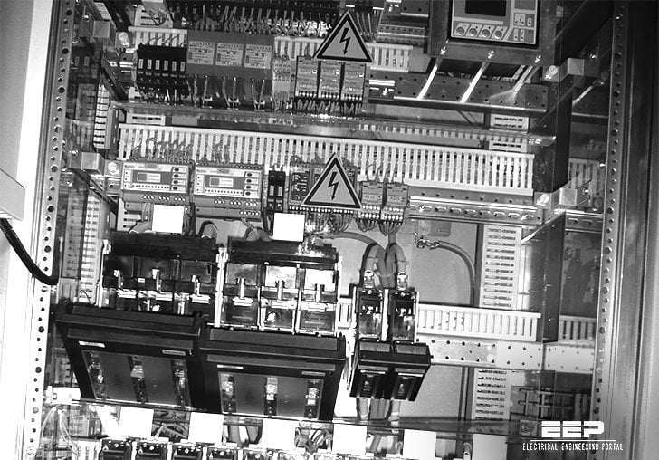
Control panel wiring is a type of electrical wiring that is used to connect various components in a control panel.
A control panel is typically used to manage and monitor the operation of machinery or equipment. It usually consists of a power supply, switches, relays, indicators, and other devices. Control panels can be found in many different industries, including manufacturing, automotive, aerospace, and more.
How Does Control Panel Wiring Work?
Control panel wiring typically uses low-voltage signals to operate the various components in the control panel. The wires are typically color-coded so that each wire can be easily identified.
Each wire must be connected to the appropriate component in order for the system to work properly.
Why Is Control Panel Wiring Important?
Control panel wiring is important because it ensures that all of the components in the control panel are properly connected and operating as intended.
If any of the wires are not connected correctly, it could cause problems with the operation of the equipment or machinery that the control panel is controlling.
Now that you know more about control panel wiring, you can see why it’s so important to make sure that all of the wires are properly connected before operating any machinery or equipment. If you have any further questions about this topic, please feel free to ask us in the comments section below!

Credit: stock.adobe.com
What is Control Panel in Substation?
A control panel is a device that houses all of the necessary components to operate a substation. This can include circuit breakers, relays, transformers, and other electrical equipment. The control panel allows for easy monitoring and control of the substation.
What is the Difference between Control Panel And Relay Panel?
There are a few key differences between control panels and relay panels. First, control panels tend to be more complex, with more features and options than relay panels. Second, control panels typically have a display screen that shows information about the system, while relay panels do not.
Finally, control panels may have a built-in power supply, while relay panels will need an external power source.
What Type of Wire is Used in Control Panels?
In control panels, wire is used to connect various electrical components and devices. The type of wire used depends on the application and the environment in which the control panel will be used. For example, in industrial applications where there is a risk of fire or explosion, special fire-resistant or flame-retardant wire may be required.
In other cases, such as when the control panel will be exposed to harsh weather conditions, waterproof or UV-resistant wire may be necessary.
What are the Standards for Electrical Substations?
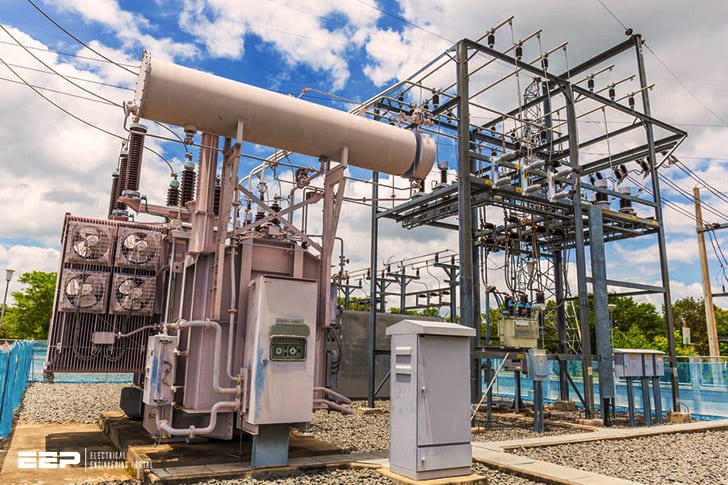
An electrical substation is a facility where electricity is generated, transmitted, and distributed to consumers. It includes transformers that change voltage levels, circuit breakers and switches that protect equipment and interrupt the flow of electricity in case of a problem, and other devices.
There are many different standards for substations around the world.
In North America, the Institute of Electrical and Electronics Engineers (IEEE) has published several standards relating to substations, including IEEE Standard 693-2016, Guide for Substation Physical Design. This standard covers aspects such as layout, clearances, fencing, lighting, drainage, fire protection, security systems, and earthing (grounding).
In Europe, the International Electrotechnical Commission (IEC) has published IEC 61850 series of standards for substation automation.
These standards define protocols for communication between various devices in a substation (e.g., sensors, actuators), as well as how data should be represented. The IEC 61850 standards are widely used in both new projects and retrofits of existing substations.
In addition to IEEE and IEC standards there are also many company-specific or project-specific standards that may apply to a given substation.
For example,…
Panel Control and Protection wiring Ferule and Code in Substation
Conclusion
The control panel is the central nervous system of a substation. It houses the equipment that controls, monitors, and protects the substation equipment and circuits. The layout of a control panel can vary depending on the size and complexity of the substation, but all panels share some common features.
The first thing you’ll notice about a control panel is the array of switches, dials, and gauges that cover its surface. These are the devices that operators use to monitor and control the substation equipment. Each switch or gauge corresponds to a specific piece of equipment or circuit in the substation.
For example, one switch might turn on a circuit breaker while another switch might activate an alarm system.
In addition to switches and gauges, a control panel also contains several other types of devices. These include meters that measure voltage and current levels, sensors that detect faults in electrical equipment, and relays that automatically disconnect circuits when problems are detected.


