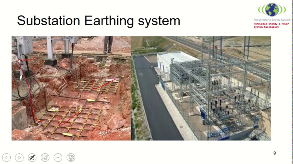
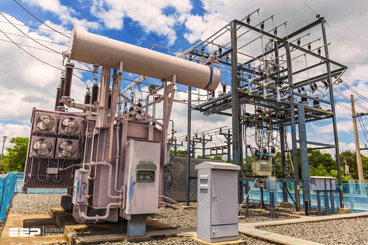
A substation earthing system is a system of electrical grounding that provides a safe path for electricity to flow in the event of a power outage or other emergency. The system consists of metal rods or plates buried in the ground, which are connected to the electrical grid and other structures in the substation. Earthing systems are designed to protect people and equipment from electrocution, fires, and explosions.
Substation Earth Grid Resistance Calculation as per IEEE-80 Standards
An earthing system is a critical part of any electrical substation. It provides a safe path for currents to flow to ground, preventing dangerous voltage buildup that could lead to fires or electrocution. There are many different types of earthing systems, each with its own advantages and disadvantages.
The most common type of earthing system is the rod-and-plate system. This system uses metal rods buried in the ground to dissipate current into the earth. Rod-and-plate systems are typically used in areas with high soil resistivity, such as deserts or rocky terrain.
Another type of earthing system is the grid system. This system uses a network of metal wires buried in the ground to dissipate current into the earth. Grid systems are typically used in areas with lower soil resistivity, such as grassy fields or sandy beaches.
Substation Earthing Pdf
Most of us are familiar with the term “earthing” or “grounding.” It is a common practice to connect electrical equipment and devices to the earth (or ground) in order to dissipate any static charge that may have accumulated on them. This is especially important for sensitive electronic equipment like computers, which can be damaged by even a small static discharge.
Earthing or grounding of substations is similarly important, but the earthing system used must be designed specifically for the substation environment. The soil characteristics at the substation site must be taken into account, as well as the size and type of equipment to be grounded. Earthing systems must also comply with safety standards set by national and international organizations.
A well-designed earthing system for a substation will provide a low impedance path to ground that will safely dissipate any fault currents that may flow through it. It should also be resistant to corrosion and other environmental factors.
Substation Earthing Ppt
There are many types of earthing systems used in electrical substations. The most common type is the plate earthing system. This system uses one or more metal plates buried in the ground to provide a low impedance path for current to flow to the earth.
Plate earthing systems are typically used in areas where the soil has a high resistivity, such as in desert regions. Another type of earthing system used in substations is the rod earthing system. This system uses one or more metal rods driven into the ground to provide a low impedance path for current to flow to the earth.
Rod earthing systems are typically used in areas where the soil has a low resistivity, such as near rivers or lakes.
Substation Earthing System Design Calculations
When it comes to substation earthing system design, there are many factors that need to be taken into account in order to ensure a safe and reliable system. Some of the most important calculations that need to be made include:
1) The resistivity of the soil in the area.
This is one of the most important factors as it will determine how well the earthing system can dissipate any fault current. A higher resistivity means that more current will flow through the soil and this can lead to problems such as dangerous voltage levels or even fires.
2) The depth of burial for any earthing electrodes.
This needs to be deep enough so that they are not affected by any surface changes (such as drought or flooding) but also shallow enough so that they can be easily accessed for maintenance.
3) The size and spacing of earthing electrodes. This needs to be carefully considered as too much spacing will mean less effective dissipation of fault current while too little spacing could lead to problems with interference between different parts of the system.
4) The type of backfill material used around earthing electrodes. This should be chosen carefully as some materials (such as concrete) can actually increase the resistivity of the soil and reduce the effectiveness of the system.
Materials Used for Substation Earthing
Earthing is a critical part of any electrical substation, as it helps to ensure the safety of both workers and equipment. There are a variety of materials that can be used for earthing, including copper, aluminium, galvanized steel and even concrete. The type of material used will typically depend on the soil conditions and the size of the substation.
Copper is one of the most popular materials used for earthing, as it has a high conductivity and resistance to corrosion. Aluminium is also a good choice for earthing due to its low cost and high conductivity. Galvanized steel may be used in some cases, but it can corrode over time so it is not always the best option.
Concrete can also be used for earthing purposes, but it must be properly reinforced to withstand the forces involved.
Substation Earthing Resistance Value
When it comes to electrical substations, the earthing resistance value is extremely important. This value represents the amount of resistance that exists between the grounding system and the earth. The lower the earthing resistance value, the better.
There are a variety of factors that can affect a substation’s earthing resistance value. Some of these include the type of soil present, how well the grounding system has been installed, and even weather conditions.
It’s important for substations to have a low earthing resistance value because this helps to ensure safety.
If there is too much resistance, it could lead to problems like voltage spikes or even fire.
There are several methods that can be used to test a substation’s earthing resistance value. The most common is called the four-terminal method.
This involves placing four electrodes in the ground and measuring the voltage between them.
The results of an earthing resistance test can help engineers determine if a substation is safe or not. If the value is too high, they may need to make changes to improve safety.
Earthing Mesh Substation
An earthing mesh is a type of substation used to provide safe electrical grounding for power distribution systems. The earthing mesh is made up of a conductive material, typically copper or aluminum, that is buried in the ground and connected to the power system’s grounding electrodes. The mesh provides a low-impedance path for currents to flow into the ground, thereby reducing the risk of electrocution or fire in the event of a fault.

Credit: www.pinterest.com
What is Earthing in a Substation?
In an electrical substation, earthing (or grounding) refers to the deliberate connection of a conductor to the ground for safety reasons. The main purpose of earthing in a substation is to protect people and equipment from dangerous voltages that may be present due to faults or other conditions.
Earthing can also help to reduce the risk of fire and explosion by providing a path for current to flow safely away from sensitive equipment.
In some cases, earthing may also be used to reduce interference from electromagnetic fields.
There are several different types of earthing systems that can be used in a substation, each with its own advantages and disadvantages. The most common type is called plate earthing, which uses metal plates buried in the ground to create a low-resistance path for current flow.
Other types of earthing include rod earthing, grid earthing, and mat earthing.
Why is Substation Earthing Important?
Substation earthing is important for several reasons. First, it provides a safe path for electricity to travel in the event of a fault. Second, it protects equipment and people from electrical shock.
Third, it helps to dissipate static charge that can build up on equipment. Fourth, earthing can provide protection from electromagnetic interference (EMI).
What are the 3 Earthing Systems?
There are three types of earthing systems which are commonly used. These are the rod, plate and mat earthing systems. Each type has its own advantages and disadvantages which should be considered before selecting a system for a particular application.
The rod earthing system is the most common type of system used. It consists of a metal rod driven into the ground and connected to the electrical system via a conductor. The advantages of this system include its simplicity and low cost.
However, it is less effective than other types of earthing systems in areas with high soil resistivity or where there is a lot of vegetation present.
The plate earthing system consists of one or more metal plates buried in the ground and connected to the electrical system via conductors. This type of system is more effective than the rod earthing system in areas with high soil resistivity or where there is a lot of vegetation present.
However, it is more expensive than the rod earthing system due to the need for multiple metal plates.
The mat earthing system consists of a metal mesh buried in the ground and connected to the electrical system via conductors. This type ofsystem offers good all-round performance as it effectively covers large areas with high soil resistivity or where there is a lot of vegetation present.
How Many Earth Pits Required for Substation?
The number of earth pits required for a substation will depend on the size and voltage of the substation. A small substation may only require one or two earth pits, while a large substation could require several hundred. The voltage of the substation also plays a role in determining the number of earth pits required, as higher voltages require more grounding to ensure safety.
Conclusion
An earthing system is a critical component of every substation. It provides a safe path to ground for fault current, allowing the electrical equipment to be safely operated. An earthing system must be designed and installed properly in order to function correctly.
This blog post discusses the basics of substation earthing systems and how they work.


