Substation equipment symbols are the standard symbols used to represent various types of electrical equipment in a substation. The symbols are usually drawn on a one-line diagram or a floor plan.
If you work in the electrical industry, then you know that substation equipment symbols are very important. They help you to identify the different pieces of equipment in a substation and understand their function. In this blog post, we will take a look at some of the most common substation equipment symbols and what they mean.
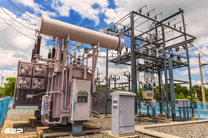
The first symbol is the transformer. This is a device that transforms high-voltage electricity into low-voltage electricity. It is an essential piece of equipment in any substation.
The next symbol is the circuit breaker. This is a device that breaks an electrical circuit when there is an overload or short circuit. Circuit breakers are used to protect equipment from damage caused by excessive current flows.
The last symbol we will discuss is the switchgear. Switchgear is used to control, protect, and isolate electrical equipment. It consists of switches, fuses, and other devices that allow electricians to safely work on electrical systems.
Symbols of substation equipments
Electrical Substation Components Pdf
In an electrical substation, various components work together to supply electricity to end-users. These components include power transformers, circuit breakers, busbars, and more. Let’s take a closer look at each of these important substation components.
Power transformers are used to change the voltage of electricity passing through the substation. This is necessary because the voltage needs to be increased or decreased for different parts of the grid. For example, electricity coming from a power plant will have a high voltage, but it needs to be lowered before it can be used in homes and businesses.
Circuit breakers are used to protect equipment in the substation from damage due to overloads or faults in the system. When an overload or fault occurs, circuit breakers will automatically disconnect the equipment from the power source to prevent damage.
Busbars are metal bars that conduct electricity within the substation.
They are often made of copper or aluminum and carry large amounts of current. Busbars connect all of the equipment in the substation together so that electricity can flow freely between them.
Other important components in an electrical substation include:
• Protective relays: These devices monitor conditions in the substation and provide protection against faults by automatically disconnecting equipment when necessary.
• Metering devices: These devices measure various parameters such as voltage, current, and power factor so that operators can monitor conditions in the substation.
Substation Symbol Autocad
In any kind of electrical engineering, it is important to be able to visualize the different components that make up a system. This is especially true when dealing with high voltage systems, where a mistake can be very costly. One way to help with this visualization is to use standard symbols for the different components.
When it comes to substations, there are a few key symbols that are used in AutoCAD.
The first symbol is the power transformer. This is shown as two circles with a line between them.
The line indicates the primary winding, while the circles represent the secondary windings. The second symbol is the circuit breaker. This is shown as a rectangle with two lines inside of it.
These lines represent the contacts that open and close the circuit breaker.
The third symbol is the busbar. This is shown as a horizontal or vertical bar with two lines running parallel to it.
These lines indicate the conductors that carry the current from one side of the busbar to the other. The fourth symbol is the grounding electrode. This is shown as a circle with a ground symbol inside of it.
This indicates that this point should be connected to ground in order to dissipate any excess voltage.
These are just four of the most commonly used symbols in AutoCAD for substations.
Substation Components And Their Functions Ppt
A substation is a critical part of the electrical grid. Without substations, the electricity that powers our homes and businesses would be unable to flow. Substations take the high-voltage electricity from power plants and transform it into the lower voltages that are used in homes and businesses.
There are four main components to every substation: transformers, breakers, capacitors, and ground rods. Each plays an important role in ensuring that electricity flows safely and efficiently through the grid.
Transformers: Transformers are responsible for changing the voltage of electricity as it flows through the substation.
By raising or lowering the voltage, transformers can help regulate the flow of electricity and prevent overloaded circuits.
Breakers: Breakers protect circuits from overloads by automatically disconnecting them when too much current is flowing through them. This prevents damage to equipment and keeps people safe from electrical shocks.
Capacitors: Capacitors store energy that can be released back into the circuit when needed. This helps to even out fluctuations in voltage and keep the flow of electricity steady. Ground Rods: Ground rods provide a path for excess current to flow into the earth, where it is harmlessly dissipated.
Introduction to Substation Equipment
A substation is a crucial part of the electrical grid, providing a link between high-voltage transmission lines and lower-voltage distribution lines. Substations come in a variety of shapes and sizes, but all contain common pieces of equipment that perform essential functions.
The first piece of equipment in a substation is the transformer.
The transformer steps down the voltage from the high-voltage transmission line to a level that can be used by the distribution lines. The transformer also includes tap changers that allow for fine adjustments to the output voltage.
The second piece of equipment found in a substation is the switchgear.
The switchgear controls the flow of electricity through the substation and protects equipment from damage due to overloads or faults. Circuit breakers are an important part of the switchgear, breaking the circuit when an overload or fault is detected. Other components of the switchgear include disconnect switches, fuses, and ground switches.
Substations also contain control equipment that allows operators to remotely monitor and control the substation’s operations. This equipment includes metering devices that measure voltage, current, and power levels; relays that send signals to other parts of the grid; and communication devices that allow operators to communicate with personnel at other locations.

Credit: www.nytimes.com
What are the Standard Symbols of Equipment Used in Substation?
There are a variety of standard symbols that are used to represent equipment in a substation. These symbols are typically found on electrical drawings and schematics. Some of the most common symbols include:
-Transformers: A transformer is typically represented by a rectangle with an “X” inside. This symbol indicates the primary and secondary windings of the transformer.
-Circuit breakers: A circuit breaker is typically represented by a rectangle with a “B” inside.
This symbol indicates the main contacts, coil, and auxiliary contacts of the breaker.
-Disconnect switches: A disconnect switch is typically represented by a rectangle with a “D” inside. This symbol indicates the main contacts and auxiliary contacts of the switch.
-Busbars: A busbar is typically represented by a horizontal or vertical line. This symbol represents the conductor that carries electricity between two points in a substation.
What are the 5 Electrical Symbols?
Electrical symbols are the shapes and lines that are used to represent different electrical components on a drawing or schematic. There are over 500 different electrical symbols in use today, but only a handful are used regularly. The five most common electrical symbols are:
1) Resistor: A resistor is an electronic component that resists the flow of electricity. It is typically represented by a zigzag line.
2) Capacitor: A capacitor is an electronic component that stores electric charge.
It is typically represented by two parallel lines.
3) Inductor: An inductor is an electronic component that inducts (or opposes) the flow of electricity. It is typically represented by a coil of wire.
4) Transistor: A transistor is an electronic device that can amplify or switch electronic signals. It is typically represented by a triangle with two crossed lines.
5) Diode: A diode is an electronic device that allows electricity to flow in one direction only.
It is typically represented by an arrowhead pointing in the direction of current flow.
What are the Three Types of Substations?
A substation is an electrical installation where voltage is transformed from high to low, or the reverse. Substations may also be used to change alternating current (AC) to direct current (DC) or vice versa. These three types of substations are air-insulated, gas-insulated and liquid-filled.
Air-insulated substations (AISs) use air as an insulator between live parts of the equipment and ground. AISs are the most common type of substation and have been in use for over a century. They are typically used at voltages below 72 kV.
Gas-insulated substations (GISs) use sulfur hexafluoride (SF6) or some other dielectric gas as the insulator between live parts of the equipment and ground instead of air. GISs were developed in the 1950s and 1960s as an alternative to AISs, and they began being used commercially in the 1970s. GIS technology has advanced significantly since then, making them more reliable than ever before.
GISs can be used at any voltage level up to765 kV.
Liquid-filled substations (LFSs) use oil or another liquid as an insulator between live parts of the equipment and ground instead of air like AIS do, or SF6 like GIS do . LFS were developed before AIS or GISTech , in around 1890 .
The first large scale installation was New York’s Pearl Street Station . Nowadays , however , due largely space -saving considerations , very few new LFS are constructed . LFS continue to operate very effectively where they have been installed such as Russia , Canada , Brazil etc .
Oil -filled transformers can be found almost anywhere there is electricity generation transmission & distribution infrastructure .
What is Substation Panel Called?
A substation panel, also known as a distribution panel, is a device that distributes electricity to a home or business. It is typically located in the basement or garage. The panel contains circuit breakers that protect the electrical circuits in the event of an overload.
Conclusion
Substation equipment symbols are used to represent various electrical and electronic devices in a substation. These symbols are usually drawn on a drawing board or whiteboard so that all the engineers can see them and understand their meaning. The most common substation equipment symbols are: transformer, switchgear, circuit breaker, bus bar, capacitor bank, power transformer, current transformer, potential transformer, impedance relay, voltage relay, overcurrent relay, earth fault relay etc.


