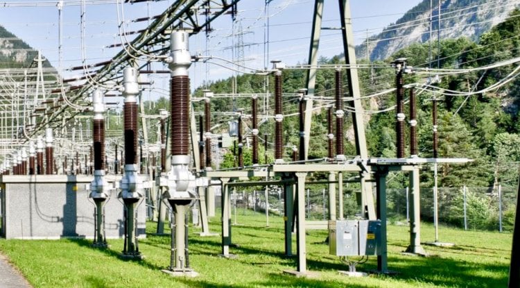
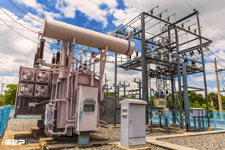
A substation grounding calculation is a mathematical way of working out the best place to put ground rods in order to protect people and equipment from electrical faults. It involves looking at factors such as the soil type, the depth of the water table and the size of the substation. The calculation is also known as a ‘grounding resistance test’ or a ‘soil resistivity test’.
Substation Earth Grid Resistance Calculation as per IEEE-80 Standards
Substation grounding calculation is a critical part of ensuring the safety and reliability of your substation. There are many factors to consider when performing this calculation, including soil resistivity, electrode spacing, and more. In this blog post, we’ll discuss everything you need to know about substation grounding calculation.
Ieee 80 Earthing Calculation Excel
IEEE 80 earthing calculation excel is an online tool that helps you to calculate the required amount of earthing for your electrical installation. The calculator takes into account the voltage, phase and frequency of your system as well as the length of conductor used. It also provides guidance on how to connect your earthing system to the mains supply.
Substation Grounding Ppt
As an electrical engineer, one of the most important aspects of your job is ensuring that substations are properly grounded. Grounding protects against voltage surges and provides a safe path for current to flow in the event of a fault. It is essential that all engineers have a good understanding of how to design and implement an effective grounding system.
This PowerPoint presentation will provide you with a detailed overview of substation grounding principles and practices. You will learn about the different types of grounding systems, their advantages and disadvantages, and how to select the best option for your application. Additionally, this presentation includes several case studies highlighting successful substation grounding projects from around the world.
Grounding Calculation Excel
Most people are familiar with the term “grounding” in relation to electricity. Grounding provides a safe path for electrical current to follow in the event of a short circuit or other problem. A good grounding system protects people and equipment from damage by safely carrying off excess current.
There are many factors that must be considered when designing a grounding system, including the type of soil, the depth of bury, and the size and type of conductor. All of these factors must be taken into account to ensure that the grounding system will work properly and provide adequate protection.
Grounding calculations can be complex, but there are some great resources available to help make the process easier.
One such resource is an Excel spreadsheet that can be used to input all of the necessary data and generate a report showing the recommended design for your particular application. This spreadsheet is available for free from several sources on the internet.
If you are responsible for designing a grounding system, or if you just want to learn more about how they work, be sure to check out this helpful tool!
Earthing Calculation Formula
The earthing calculation formula is used to determine the amount of current that will flow through a conductor when it is connected to an earth electrode. The formula is based on the resistivity of the soil and the length of the conductor.
Substation Grounding Pdf
Most of us are unaware of the substation grounding pdf. It is a document prepared by the electric utility company which contains all the information regarding the substation grounding system. This document is very important for the safety of the public and the workers who are working in or near the substation.
The substation grounding pdf provides detailed information about the different types of grounding systems, their advantages and disadvantages, and how to properly install them.
Earthing Calculation Formula Pdf
If you’re looking for a detailed explanation of how to calculate earthing, you’ve come to the right place. This blog post will provide a step-by-step guide on how to properly calculate earthing using different formulas.
First, it’s important to understand the basics of what earthing is and why it’s important.
Earthing is basically the process of creating a conductive path between an electrical device and the ground. This helps to protect against voltage surges and provides a safe way for electricity to flow in case of an emergency.
There are several different formulas that can be used to calculate earthing, but the most common one is known as the NEC (National Electrical Code) formula.
This formula takes into account the depth of burial, type of soil, and other factors that can affect earthing performance.
To use this formula, you’ll need to know the following information:
Depth of burial: This is the depth at which your electrical device will be buried in the ground.
The NEC recommends a minimum depth of 6 feet (1.8 meters). However, deeper depths may be required depending on your specific situation. Type of soil: The NEC divides soil types into four categories: sandy, loamy, clayey, and rocky.
Each type of soil has different electrical properties that can affect how well earthing works. Other factors: There are other factors that can influence earthing performance, such as moisture content and compaction level of the soil. These factors should be taken into account when choosing an appropriate earthing system for your needs.
The NEC formula for calculating earth resistance is as follows:
R= [(12/(K*D))*ln(A/B)] + C where R = Earth resistance in ohms K = Soil conductivity in mS/m D = Depth of burial in meters A = Area surrounding conductor in square meters B = Distance from conductor to remote earth electrodes C = Resistance contributed by remote earth electrodes
For example purposes, let’s say we want to calculate the earth resistance for a situation where we’re burying our electrical device at a depth of 8 feet (2.4 meters) in sandy soil with moist conditions and good compaction levels .
We also have two remote earth electrodes installed 100 feet (30 meters) away from our conductor . Using these values , we would plug them into our equation like so :
R= [(12/(0 .
Bs 7430 Earthing Calculation Excel
The Excel spreadsheet provided on this page can be used to calculate the design parameters for a variety of earthing systems according to BS 7430. The user simply inputs the relevant data into the yellow cells, and the spreadsheet performs all of the necessary calculations automatically.
This spreadsheet is particularly useful for designing earthing systems for buildings, as it takes into account a number of different factors that need to be considered in such cases.
For example, wheninputting data relating to the soil resistivity, the user can select from a list of common soil types or input their own value. This ensures that the results are as accurate as possible.
In addition, the spreadsheet also provides information on how to achieve good earth contact by using either copper-clad steel or galvanised steel rods.
This is important in order to ensure that your system meets all of the requirements set out in BS 7430.
Earthing Calculation Software
There are many different ways to calculate the earthing system for a project. The most common methods used in industry today are the National Electrical Code (NEC) and the International Electrotechnical Commission (IEC) standards. Both of these sets of requirements use different formulas to determine the size and number of electrodes needed for a given earthing system.
However, there are also software programs available that can help with this process.
One such program is Earthing Calculation Software from Schonstedt Instrument Company. This program uses NEC and IEC formulas to determine the size and number of electrodes needed for a variety of earthing systems.
It also includes a database of over 1000 soil resistivity values from around the world, which can be used to input into the program for more accurate results.
If you’re looking for an easy way to calculate your earthing system requirements, then Earthing Calculation Software is definitely worth considering.

Credit: esgrounding.com
How Do You Calculate Grounding?
When it comes to electrical work, grounding is an important safety measure. Grounding provides a path for electricity to follow in the event of a short circuit or other problem, which can help prevent electrocution and damage to property. But how do you calculate grounding?
The first step is to identify the point of ground potential. This is usually done by finding the earth’s natural voltage, also known as the ground potential reference (GPR). The GPR can be found by measuring the voltage between two points on the earth’s surface.
Once the GPR has been found, all other voltages can be referenced to it.
Next, you need to determine what type of conductor will be used for grounding. The most common type of conductor is copper, but other materials such as aluminum or steel can also be used.
The size of the conductor will depend on the amount of current that needs to be carried and the length of the run.
For example, if you are running a line from an electrical panel to a light fixture, 14 AWG copper wire would typically be used. This wire has a diameter of 0.064 inches (1.63 mm) and can carry up to 15 amps of current over a distance of 50 feet (15 m).
If you were running a line from an electrical panel to an air conditioner unit, however, you would need to use 4 AWG copper wire due to the higher amount of current required by air conditioners (up to 60 amps). This wire has a diameter of 0.25 inches (6.35 mm) and can carry up to 85 amps over a shorter distance of 30 feet (9 m).
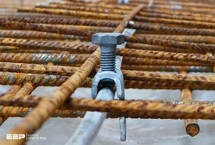
After determining what size conductor is needed, you must then select an appropriate method for attaching it to both the electrical panel and whatever device you’re grounding (e.g., light fixture or air conditioner unit).
There are various ways this can be done depending on your specific application but one common method is using clamp-type connectors which securely attach around both conductors with screws or bolts. Once everything is properly connected, your grounding system should be operational!
What is the Grounding Standard for Ieee Substation?
The grounding standard for IEEE substation is to have a minimum of two electrodes, each placed at least 10 feet (3 meters) away from the other, and driven into the earth to a depth of at least 8 feet (2.4 meters). The electrodes must be made of copper or another corrosion-resistant material.
How Do You Calculate Substation Earthing?
There are a few ways to calculate substation earthing. One way is to use the American Society of Civil Engineers (ASCE) 7-2010 Standard Minimum Design Loads for Buildings and Other Structures. This standard provides guidance on calculating the design loads, including Dead, Live, Wind, Snow, Rain and Earthquake loads.
Another way to calculate substation earthing is by using the National Electric Code (NEC). The NEC provides requirements for grounding and bonding of electrical systems. It also provides information on how to calculate the size and depth of earth electrodes.
Once you have calculated the design loads and the NEC requirements, you can then select an appropriate earthing system for your substation. There are many different types of earthing systems available on the market today. Some common types include rod or plate electrodes, ground grids, soil resistivity testing and more.
It is important to select an earthing system that is suitable for your specific application and site conditions. If you are unsure about which system to choose, it is always best to consult with a qualified engineer who can help you select the most appropriate option for your needs.
What is the Grounding Resistance of a Substation?
Grounding resistance is the measure of a material’s ability to conduct an electrical current. The lower the grounding resistance, the better the material will be at conducting an electrical current. The grounding resistance of a substation is important because it determines how well the substation can dissipate any excess electricity that may build up within its structure.
Excess electricity can be dangerous and cause damage to equipment, so it is important for substations to have a low grounding resistance in order to protect against this potential hazard.
Conclusion
Substation grounding is a critical part of the electrical system. The purpose of substation grounding is to provide a safe path for fault current to flow to ground and to protect equipment and personnel from voltage surges. There are many factors that need to be considered when designing a substation grounding system, including the type of soil, the amount of rainfall, the number of Lightning flashes in the area, and more.
This blog post provides an overview of the calculation methods used to determine the size and type of grounding system needed for a substation.


