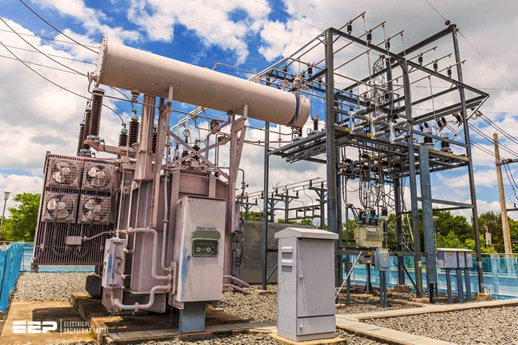
The purpose of grounding a substation is to provide a safe path for current to flow in the event of a fault. The most common type of grounding system used at substations is the electrode system, which consists of one or more metal rods driven into the ground. The depth and spacing of the electrodes depends on the soil conditions and the amount of current flowing through the system.
One of the most important aspects of electrical substation design is grounding. The purpose of grounding is to provide a safe path for current to flow in the event of a fault. Grounding also helps protect equipment from voltage surges.
There are several types of grounding systems that can be used in a substation, and the type that is best suited for a particular application depends on many factors. In this blog post, we will discuss some of the basics of substation grounding and provide an overview of the different types of systems that are available.
lecture 3, Substation grounding system
Ieee Guide for Safety in Ac Substation Grounding Pdf
The IEEE guide for safety in AC substation grounding provides detailed information on the design and implementation of safe grounding practices in AC substation environments. The guide covers a wide range of topics, including: the selection and sizing of ground electrodes, the use of cathodic protection to control corrosion, the installation and testing of ground grids, and the monitoring and maintenance of ground systems. It also includes a section on earthing for lightning protection.
Substation Grounding Ppt
Substation Grounding Ppt
When it comes to substation grounding, there are many factors that must be considered. The purpose of this blog post is to provide detailed information about substation grounding and how it can impact the overall performance of your electrical system.
There are two types of grounding systems used in substations: direct and indirect. Direct grounding involves connecting the phase conductors directly to the earth. Indirect grounding, on the other hand, uses a ground grid or electrode to provide a path for current flow back to the earth.
The type of soil in which the substation is located plays a big role in determining which type of grounding system is best suited for that particular location. For example, sandy or rocky soil generally has a high resistivity, making it more difficult for current to flow through. In these cases, an indirect grounding system would be more effective because it provides a larger surface area for current to flow over.
Another factor that must be considered when designing a substation grounding system is the possibility of corrosion. Corrosion can occur when there is an electrolytic reaction between different metals in contact with each other (e.g., copper and aluminum). This reaction can produce harmful gases that can damage equipment and cause safety hazards.
To prevent this from happening, special coatings or materials may be used on underground metal parts or electrodes .
Ieee Std 80 Pdf
What is IEEE STD 80?
IEEE STD 80 is the standard for safety in electrical equipment. It covers a wide range of topics, from design to installation to maintenance.
The goal of the standard is to prevent fires and electrocutions in homes and businesses.
IEEE STD 80 was first published in 1974, and has been updated several times since then. The most recent version was published in 2018.
The standard covers a wide range of electrical equipment, including:
-Circuit breakers
-Fuses
-Switches
-Outlets
-Cords and plugs
Ieee 80 Earthing Calculation Excel
The IEEE 80 earthing calculation is a method used to determine the safe and effective earthing for electrical systems. This calculation is based on the maximum allowable voltage drop across an earth conductor, and takes into account the impedance of the soil and any other resistive or capacitive effects. The IEEE 80 calculation is performed by first determining the maximum allowable voltage drop across the earth conductor, and then calculating the required size of the earth electrode.
There are a number of factors that must be considered in order to ensure accurate results from the IEEE 80 earthing calculation. These include:
-The type of soil in which the electrode will be installed.
Different soils have different resistivity values, which will affect the overall impedance of the earth system.
-The depth at which the electrode will be installed. The deeper an electrode is buried, the lower its impedance will be.
-The length of conductor used to connect the electrode to grounding points within the system. The longerthe conductor,the higher its impedance will be. -Any additional resistive or capacitive elements that may be present within the system (such as transformers or surge arrestors).
In order to accurately perform an IEEE 80 earthing calculation, it is important to have access to accurate data regarding these various factors. Once this information has been gathered, it can then be entered into a specialized software program designed for performing such calculations. Doing so will allow for quick and easy determination of an appropriate size for an earth electrode, as well as providing insight into potential sources of error that could lead to inaccurate results.
Ieee Grounding (Standard Pdf)
As the name suggests, IEEE Grounding is the process of connecting an electrical system to the ground. This is done to protect the equipment and people using it from electric shock. It also helps to dissipate static electricity and provides a path for current to flow in the event of a short circuit.
There are two types of grounding: direct and indirect. Direct grounding means that there is a physical connection between the electrical system and the ground. Indirect grounding means that there is no physical connection but instead, the electrical system is connected to another conductor which itself is connected to the ground.
Types of Earthing in Substation
There are three types of earthing in substation:
1. Rod Earthing:
This is the most common type of earthing.
A rod or pipe is driven into the ground and provides a low impedance connection to the earth. The depth of the rod depends on the soil conditions but is typically 3-4m. The resistance of this type of earthing can be as low as 10 ohms.
2. Plate Earthing:
A metal plate is buried in the ground and provides a low impedance connection to the earth. The size of the plate depends on the soil conditions but is typically 1m x 1m.
The resistance of this type of earthing can be as low as 100 ohms.
3. Mesh Earthing:
A metal mesh is buried in the ground and provides a low impedance connection to the earth.
The mesh can be made from copper or galvanised steel and must have a mesh size less than 50mm2 .
Substation Ground Grid
Assuming you would like a blog post discussing the function of a substation ground grid:
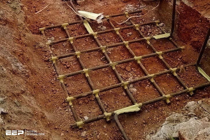
A substation ground grid is an electrical system used to provide a safe and reliable path for current to flow in the event of a fault. The grid is designed to manage the flow of current so that it does not cause damage to equipment or pose a safety hazard to personnel.
When properly designed and installed, a substation ground grid can improve the reliability of power delivery and help protect against outages.

Credit: www.powerandcables.com
How is a Substation Grounded?
A substation is a high-voltage electrical system that reduces the voltage of an alternating current (AC) to a safe level for distribution to customers. The first step in grounding a substation is to create a grid of electrodes buried in the earth. This grid forms the conductive path that will dissipate any excess charge and prevent dangerous buildup.
Next, metal rods or plates are placed at strategic points around the perimeter of the substation. These rods and plates create an additional conductive pathway for excess charge to flow into the ground. Finally, cables called “ground wires” are connected from various equipment within the substation to these external rods and plates.
This completes the circuit and provides a safe way for any surplus electricity to be discharged into the ground.
What is Common Grounding in Substation?
Common grounding in substations is the process of connecting all the metallic parts of the substation to a common electrode which is usually buried in the earth. This ensures that all these parts are at the same electrical potential, thus preventing any differences in voltage which could lead to arcing and other problems.
What is the Iec Standard for Substation Grounding?
The IEC standard for substation grounding is 60364-4-41. This standard covers the requirements for the design, installation and maintenance of electrical equipment in substations. The standard includes requirements for earthing arrangements, protective equipotential bonding and insulation coordination.
What is the Grounding Resistance of a Substation?
When it comes to the grounding resistance of a substation, there are a few key things to keep in mind. First and foremost, the grounding resistance of a substation is incredibly important when it comes to ensuring the safety of both workers and equipment. Without a proper grounding resistance, there is a much greater risk for electrical shocks and fires.
Additionally, the grounding resistance of a substation also plays a role in how well the system functions overall. A lower grounding resistance can help to improve the performance of electrical equipment and systems.
Conclusion
Substation grounding is a critical part of the electrical infrastructure. Without proper grounding, the substation and its equipment can be damaged or destroyed by severe weather or other events. Grounding also protects personnel from electrical shock.
This blog post provides an overview of substation grounding, including its purpose and how it works.


