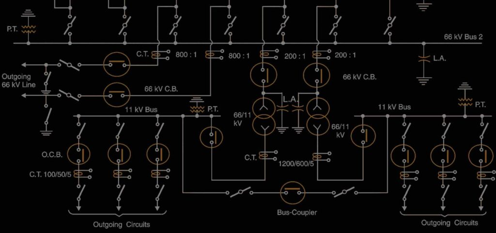
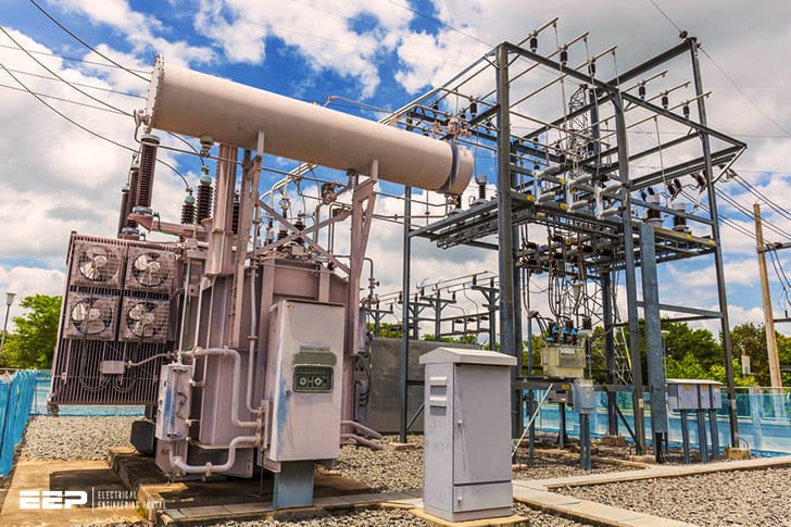
A substation layout diagram is a drawing that shows the arrangement of equipment within a substation. The diagram includes the location of power transformers, switchgear, circuit breakers, and other equipment. It also shows the path of electrical cables andbusbars between the different pieces of equipment.
A substation is an electrical installation that provides switching, protection and transformation of energy in electric power systems. Substations are generally located at the interface between transmission and distribution networks or between generation plants and either the grid or end user.
The primary purpose of a substation is to switch equipment on or off, as well as protect and isolate equipment from faults in the system.
A typical substation layout includes a switchgear, transformers, busbars and cables. The switchgear may be housed in a building, but more often it is enclosed by fencing to prevent unauthorised access.
A substation layout diagram helps you understand how the different components of a substation are arranged.
It is useful for planning purposes when designing or expanding a substation.
SINGLE LINE DIAGRAM 33KV/11KV SUBSTATION in hindi
66 Kv Substation Components
A 66 kV substation is a facility where electrical equipment is installed to facilitate the distribution of electricity at 66,000 volts. This type of substation is usually used in high-voltage transmission systems.
The main components of a 66 kV substation are:
-Transformers: Used to step down the voltage from the high-voltage transmission line to a lower voltage that can be used by consumers.
-Circuit breakers: Used to protect transformers and other equipment from damage due to faults or power surges.
-Capacitors: Used to store energy and improve power quality.
-Busbars: Conductors that carry large currents between the various pieces of equipment in the substation.
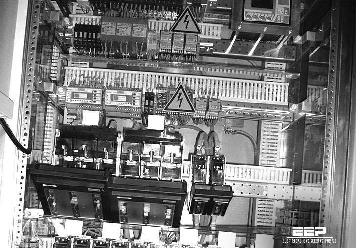
-Protective relays: Devices that monitor conditions in the substation and automatically take action if a problem is detected (e.g., trips circuit breakers).

Credit: www.youtube.com
What is Substation Layout?
A substation layout is a drawing that shows the arrangement of equipment within a substation. It typically includes a plan view of the station, as well as elevation and section views. The layout may also include detailed drawings of individual pieces of equipment.
The purpose of a substation layout is to help visualize the arrangement of equipment and how it will all fit together. This can be helpful when planning the construction of a new substation or when making changes to an existing one.
Equipment in a substation can be arranged in many different ways, depending on the specific needs of the facility.
However, there are some general principles that are typically followed. For example, larger pieces of equipment are usually placed near the perimeter of the station, while smaller items are positioned closer to the center.
In addition, high-voltage equipment is often located at the top of the station, while lower-voltage gear is placed below it.
This helps to minimize the risk of electrical hazards.
When designing a new substation layout, engineers must take into account many factors, such as local conditions, space limitations and future expansion plans.
What are the Three Types of Substations?
A substation is a power system facility where voltage is transformed from high to low, or the reverse, using transformers. Substations are also used to change the current from alternating current (AC) to direct current (DC), or vice versa. The three types of substations are transmission, distribution, and switching.
Transmission substations step-down extremely high voltages from the transmission grid and distribute it to lower voltage regional grids. They typically have few or no distributing circuits because their primary purpose is not to serve loads but rather connect sections of a very long power system. A typical voltage for a transmission substation might be 115 kV AC or 138 kV DC.
Distribution substations distribute electricity from the local transmission network to end users. These substations usually have many distribution circuits feeding several different secondary networks with various voltages ranging from 240 V single-phase up to 13 kV three-phase in North America. In other parts of the world, voltages as high as 33 kV three-phase are distributed directly to end users by means of underground cables without going through any kind of transformer station at all.
Switching stations are places where circuits are switched between different parts of the power system in order to protect equipment and restore service after faults occur.
What are the Different Types of Substation Layouts?
There are several different types of substation layouts that are used in the electrical power industry. The type of layout that is used depends on the specific needs of the utility company or other organization that owns and operates the substation. Some of the most common types of substations include radial, looped, and meshed configurations.
Radial substations are one of the simplest designs and consist of a single line running from the substation to each customer or load center. This type of configuration is typically used for low-voltage distribution systems. Looped substations are similar to radial stations, but instead of a single line running out to each load center, there are multiple lines arranged in a loop configuration.
This type of layout provides redundancy in case one line experiences an outage or other problem. Meshed substations are more complex than both radial and looped designs and consist of multiple lines running in different directions from the substation. This type of layout provides even greater redundancy than a looped system and is typically used for high-voltage transmission systems.
How Do You Design a Substation?
A substation is a critical part of the electrical grid. It is a collection of equipment that transforms high-voltage electricity from transmission lines to the lower voltages used by businesses and residences. A substation also switches electricity between different circuits and can isolate sections of the grid for maintenance.
Designing a substation requires a deep understanding of electrical engineering principles and how they are applied to real-world conditions. The first step is to understand the local power system and its voltage levels. The next step is to determine what type of equipment is needed, such as transformers, switchgear, circuit breakers, and busbars.
Once this information is gathered, engineers must select the proper locations for each piece of equipment within the substation boundaries. They also need to account for things like access roads, clearances, fire protection, and security fencing.
After all of this planning, the actual construction phase can begin.
This typically includes erecting walls or buildings to house outdoor equipment, installing underground cable ducts, and putting in place any concrete footings or pads required by law or regulation. With modern technology, many substations can now be controlled remotely which helps reduce costs and improve efficiency.
Conclusion
Layout diagrams for substations show how the equipment is arranged in the substation. The layout must be designed so that the equipment can operate safely and efficiently. The diagram shows the location of the various pieces of equipment, such as transformers, circuit breakers, and switches.
It also shows the path that electricity takes through the substation.


