Bpi in substation refers to the basic protection interface. It is a standard interface that defines how different devices within a substation communicate with each other. The Bpi interface is used to exchange information related to protection, control, measurement and status between devices.
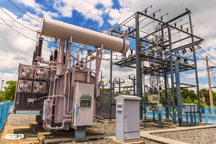
In electrical engineering, the basic principle of a substation is to receive, distribute and convert high-voltage electricity from the transmission system to the lower voltages used by consumers. The main components of a substation are transformers, switchgear and circuit breakers.
Bpi in Substation refers to the Base Plate Insulation.
It is a type of insulation that is used to protect against electrical shock. It is made of rubber or plastic and is placed between the metal base plate and the ground.
Bpi Meaning
Bpi stands for Bank of the Philippine Islands. It is one of the largest banks in the Philippines and has been in operation since 1851. The bank offers a wide range of services including savings and checking accounts, loans, credit cards, and investment products.
What is Substation Earthing
One of the most important aspects of electrical engineering is earthing or grounding. Earthing ensures the safety of people and equipment by providing a safe path for excess electricity to flow into the ground. Without earthing, electrical currents would have nowhere to go but through people or equipment, which could lead to serious injury or damage.
Substation earthing is a type of earthing that is used in substations, which are locations where electricity is transformed from one voltage to another. Substation earthing systems must be designed carefully in order to ensure the safety of those who work near the substation and the equipment within it.
The most important part of a substation earthing system is the earth electrode, which is a metal rod that is driven into the ground.
The earth electrode provides a low-resistance path for excess electricity to flow into the ground. In order for the earth electrode to work properly, it must be made of material that will not corrode over time and it must be installed correctly.
In addition to an earth electrode, a substation may also have other types of electrodes such as air termination electrodes and surface electrodes.
These electrodes provide additional paths for electricity to flow into the ground in case the earth electrode fails.
A good substation earthing system will protect people and equipment from electrical hazards while also providing reliable power transformation.
Earthing of Substation Pdf
Substations are an integral part of the electrical grid, providing a link between generation and load. The earthing system is a critical component of any substation, providing a safe path to ground for fault current and protecting equipment from voltage transients.
The purpose of this blog post is to provide detailed information about the earthing of substations.
We’ll cover the different types of earthing systems, their advantages and disadvantages, and some important design considerations.
There are three main types of earthing systems used in substations: rod-type, plate-type, and mesh-type. Rod-type earthing systems are the simplest and most common type used.
They consist of one or more metal rods driven into the ground near the substation. Plate-type earthing systems use one or more metal plates buried in the ground near the substation. Mesh-type earthing systems use a network of conductors (usually copper wire) buried in the ground around the substation to create an electrically conductive mesh.
Each type of system has its own advantages and disadvantages. Rod-type systems are simple to install but can be subject to corrosion over time. Plate-type Systems offer better protection against voltage transients but can be more difficult to install correctly.
Mesh-type Systems provide superior protection against both fault current and voltage transients but require careful design and installation to ensure proper performance.
Bus Post Insulator Manufacturers in India
There are many bus post insulator manufacturers in India that provide a variety of products for different purposes. Some of the most popular brands include:
– ABB India Limited: A leading global provider of power and automation technologies, ABB India offers a wide range of high quality bus post insulators for various applications.
– Crompton Greaves Ltd: One of the largest manufacturers and suppliers of electrical equipment in India, Crompton Greaves offers an extensive range of bus post insulators for both indoor and outdoor use.
– Larsen & Toubro Limited: A leading engineering and construction conglomerate in India, Larsen & Toubro provides a comprehensive range of bus post insulators for various industrial and commercial applications.
Importance of Earthing in Substation
Earthing in a substation is important for many reasons. It helps to ensure the safety of personnel and equipment, it minimizes the risk of fire and explosion, and it improves the efficiency of electrical systems.
Earthing provides a safe path for currents to flow to earth, which prevents dangerous voltages from building up in electrical equipment.
It also helps to dissipate static charges that can build up on surfaces.
In the event of a fault, earthing can help to prevent damage to equipment by providing a low-resistance path for current to flow safely away from sensitive components. This can minimize the risk of fire or explosion.
Earthing can also improve the efficiency of electrical systems by reducing impedance losses. When earthing is not used, currents can take circuitous paths through the system, causing unnecessary losses.
Pipe Earthing in Substation
Pipe earthing is a type of earthing system used in electrical substations. It consists of a buried pipeline, connected to an earth electrode, which is used to provide a low impedance path to ground. Pipe earthing systems are often used in areas where the soil resistivity is high and conventional earthing systems are not effective.
Materials Used for Substation Earthing
When it comes to substation earthing, there are a variety of materials that can be used depending on the application. Some of the most common materials used include copper, aluminum, and steel. Each of these materials has its own advantages and disadvantages that need to be considered when choosing the best option for your substation.
Copper is one of the most popular choices for substation earthing due to its high conductivity. This means that it can provide a low resistance path for current to flow, which is essential in ensuring proper operation of electrical equipment. Copper is also very corrosion resistant, making it ideal for use in locations where moisture or other environmental conditions could lead to degradation of other materials.
However, copper can be quite expensive compared to other options and may require more maintenance over time due to its tendency to oxidize.
Aluminum is another popular choice for substation earthing due to its high conductivity and low cost. However, aluminum is not as corrosion resistant as copper and can degrade over time if exposed to moisture or other harsh conditions.
It is important to note that aluminum will also expand and contract more than copper when exposed to changes in temperature, so care must be taken to account for this when designing an earthing system using this material.
Steel is often used in conjunction with other materials such as copper or aluminum in order to take advantage of its high strength-to-weight ratio. This makes steel an ideal choice for supporting heavier loads such as transformers or switchgear within a substation.
Additionally, steel’s lower expansion rate compared to aluminum helps minimize potential damage during thermal cycling events. While steel offers many benefits, it does have some drawbacks including a higher resistance than both copper and aluminum which can lead to increased energy losses during operation.
Substation Earthing Resistance Value
There are many variables to consider when determining the substation earthing resistance value. The size and type of earth electrodes, the soil resistivity, the depth of burial, and the water content all play a role. In addition, there are various methods for measuring earthing resistance, each with its own advantages and disadvantages.
The most important factor in determining the substation earthing resistance value is the soil resistivity. This is because the resistivity of the soil determines how much current will flow through it and how well it will conduct electricity. The higher the soil resistivity, the more current will flow through it and the greater the risk of electrical hazards.
Another important factor to consider is the depth of burial of earth electrodes. shallower electrodes are more likely to be exposed to surface moisture and may have a higher impedance than deep-buried electrodes.
Water content is also a critical factor as moist soils have lower resistivities than dry soils.
For this reason, it is important to monitor rainfall levels and take measures to prevent waterlogging around earth electrodes.In general, a lower earthing resistance value is better as it reduces the risk of electrical hazards.

Credit: www.bpienergy.com
What is Electrical Bpi?
BPI, or Building Performance Institute, is a nonprofit organization that promotes energy efficiency and sustainable building practices. BPI develops standards for home energy audits and certifies contractors who perform them. BPI-certified contractors can help you improve your home’s energy efficiency, comfort, safety, and durability.
What is the Function of Bus Post Insulator?
A bus post insulator is a device that is used to electrically isolate two conductors. It is typically used to prevent electrical shock in cases where there is a possibility of contact between live electrical circuits and people or animals. Bus post insulators are made from a variety of materials, including glass, ceramic, porcelain, and plastic.
What is Bus Post Insulator in Switchyard?
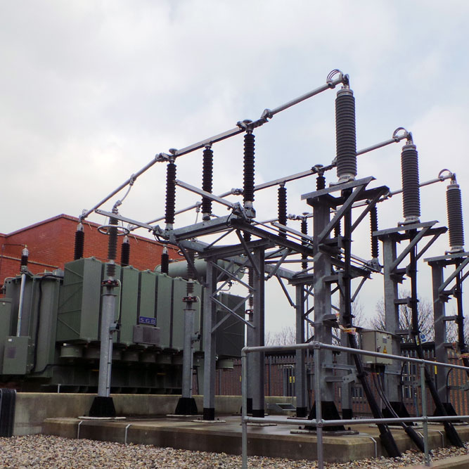
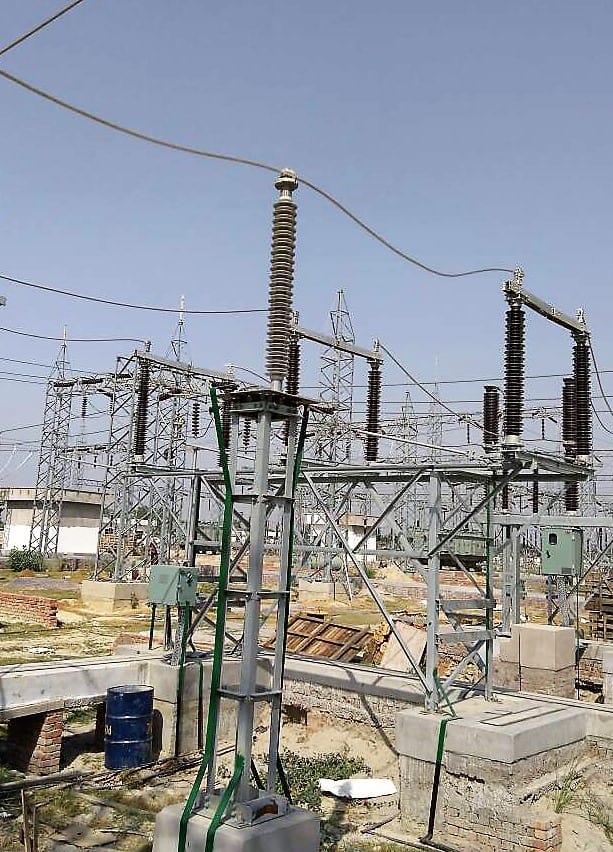
A bus post insulator is an electrical insulator that is used to support and electrically isolate a bus bar in a switchyard. A bus bar is a metal conductor that carries electric current between two or more devices. Bus post insulators are made of porcelain, glass, epoxy, or other non-conductive materials.
They are typically cylindrical in shape and have a hole in the center for the bus bar to pass through.
Bus post insulators are important components of electrical systems because they prevent dangerous arcing and short circuits. When an electrical current passes through a conductor, it creates a magnetic field around the conductor.
If this magnetic field becomes strong enough, it can cause sparks (or arcs) to jump from the conductor to nearby objects, which can damage equipment or start fires. By electrically isolating the bus bar from its surroundings, the risk of arcing is greatly reduced.
There are many different types and designs of bus post insulators, but they all serve the same basic purpose: to support and electrically isolate a bus bar.
The specific design depends on the voltage and current carrying capacity of the system, as well as other factors such as environmental conditions.
What is the Difference between a Switch Yard And a Substation?
A switchyard is a type of railway yard where locomotives and rolling stock are exchanged between tracks. A substation is an electrical facility that converts between different voltages and distributes power to end users.
Bus Post Insulator (BPI) Electrical 66/11Kv Substation Detail Explanation | All Equipments .
Conclusion
What is Bpi in Substation?
Bpi stands for Busbar Protection Index, and is a numerical value that defines the amount of protection a substation has against busbar faults. This index is used to help engineers determine the necessary level of protection for a given substation.
A higher BPI value indicates a more fault-tolerant design, while a lower BPI value indicates a less fault-tolerant design.
The calculation of Bpi takes into account several factors, including the number of buses in the substation, the type of busbars used, and the size of the substation. The most important factor in determining BPI is the number of buses in the substation; more buses means more opportunities for faults to occur.
There are two types of busbars used in substations: single-ended and double-ended. Single-ended busbars are more common and have one end connected to ground (earthing point). Double-ended busbars have both ends connected to ground, which provides better protection against faults but requires more space.
The size of a substation also affects its BPI; larger substations have more room for error and can therefore tolerate more faults before experiencing an outage.
In general, higher BPIs are desirable because they indicate a higher level of protection against busbar faults. However, there is tradeoff between cost and reliability; increasing the BPI will usually increase the cost of the substation as well.
Therefore, it is important to balance these two factors when designing or selecting a substation.


