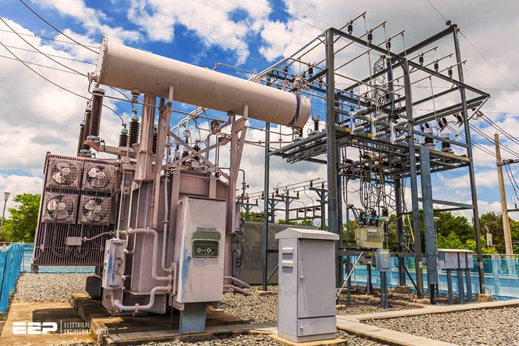
The Earth Resistance of a substation is the measure of the electrical resistance of the ground to an electrical current. It is a key factor in determining the safety and performance of an electrical system.
If you’ve ever wondered what the earth resistance for a substation is, wonder no more! In this blog post, we’ll take a quick look at this important value and what it means for substations.
Simply put, the earth resistance for a substation is the measure of how well the ground around the substation conducts electricity.
This value is important because it helps to determine how effective grounding will be for the substation. A low earth resistance means that there is a good conductive path from the substation equipment to the ground, which helps to protect against electrical faults. Conversely, a high earth resistance can indicate poor grounding and an increased risk of electrical problems.
There are several factors that can affect the earth resistance for a substation, including soil type, moisture content, and vegetation. In general, though, most Substations have an Earth Resistance between 5 and 10 ohms. This value can be measured using specialised equipment and should be checked regularly to ensure proper grounding performance.
Substation Earth Grid Resistance Calculation as per IEEE-80 Standards
Earth Resistance Test Value
What is Earth Resistance Test Value?
The earth resistance test value is a measure of the ability of the earth to resist the flow of current. It is a important parameter in the design of electrical systems and can be measured using a variety of methods.
The most common method is to use a four-point probe, which measures the voltage across a known resistance placed in the soil. The value obtained from this measurement is then used to calculate the earth resistance.
The earth resistance test value is important because it allows engineers to determine the amount of current that can safely be flowing through a given area without causing damage to equipment or injury to people.
For example, if an electrical system was designed with an earth resistance test value of 10 ohms, then it would be able to handle up to 100 amps of current before any problems would occur.
There are many factors that can affect the earth resistance test value, such as type of soil, moisture content, and compaction. In general, sandy soils have lower values than clay soils, and dry soils have lower values than wet soils.
Compacted soils also tend to have lower values than loose soils.
If you are designing an electrical system, it is important to know the earth resistance test value for the area where it will be installed. This information can help you determine what size conductor must be used and how much current can safely flow through your system.
Earth Resistance Value for Home
The Earth Resistance Value for a home is the measurement of how well the home is insulated from the ground. The higher the number, the better the insulation. This number is important because it helps to determine how much energy is required to heat or cool the home.
It also affects the amount of moisture that can enter the home, which can impact indoor air quality.
Earthing of Substation Pdf
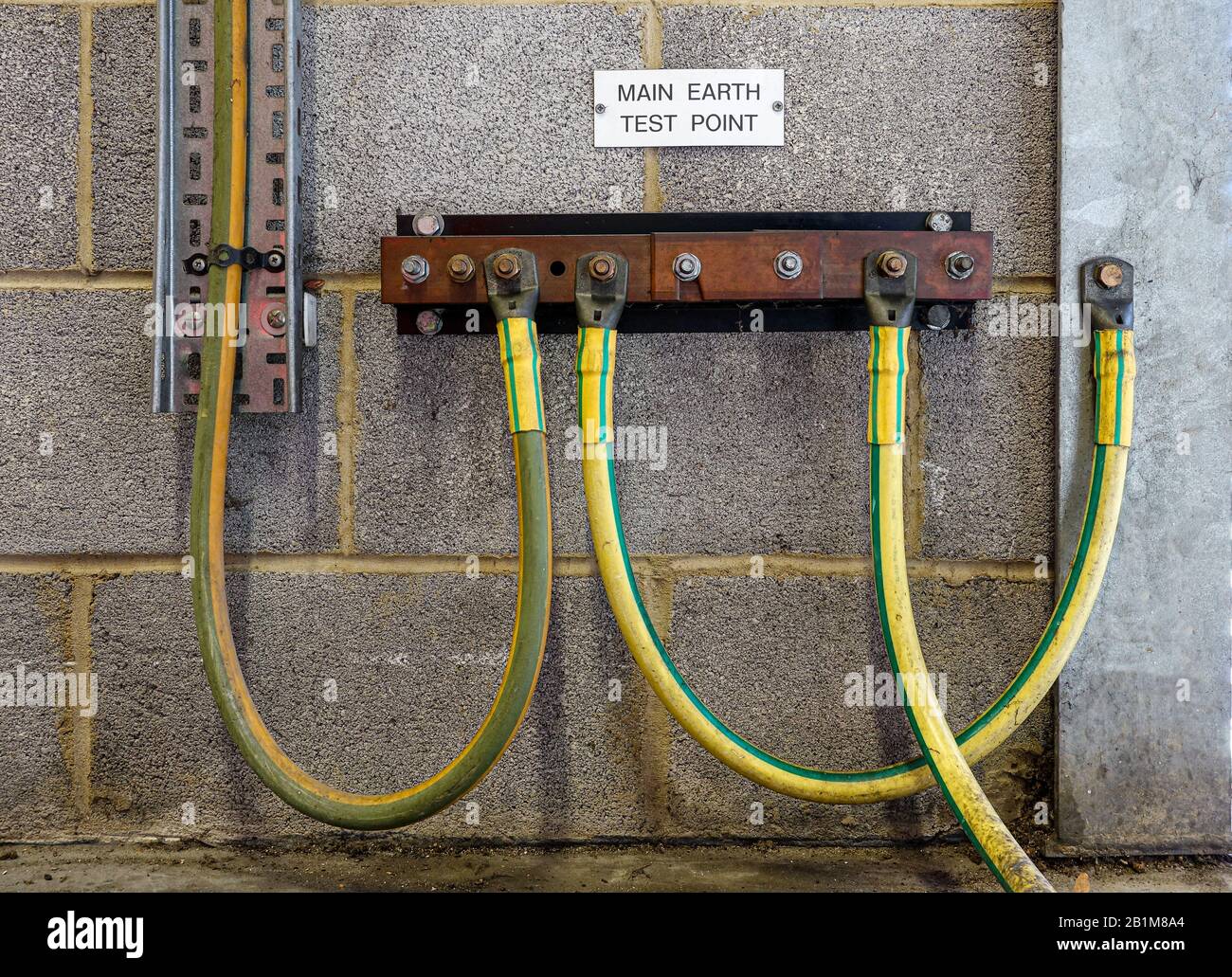
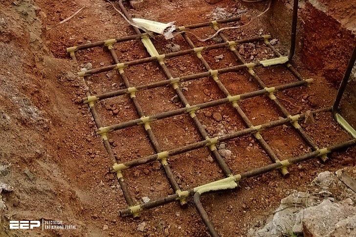
In a nutshell, substation earthing is the process of creating an electrical connection between a substation and the ground. This helps to protect both the substation and its equipment from damage due to lightning strikes or other electrical surges. Earthing also helps to dissipate any static electricity that may build up within the substation.
Earth Resistance Formula
If you are working with electrical wiring, you need to be aware of the earth resistance formula. This formula is used to calculate the amount of resistance that the earth offers to electrical current. The higher the number, the more resistant the earth is.
The earth resistance formula is: R=ρL/A
Where:
R= Earth Resistance
ρ= Soil resistivity
L= Length of conductor
A= Cross sectional area of conductor
For most applications, you will want to keep the soil resistivity as low as possible. This can be done by using a wire with a larger cross sectional area or by keeping the length of the conductor short.
Earthing Resistance Value As Per Iec
Earthing resistance value as per IEC:
The earth connection of an electrical system is designed to limit the voltage that can be imposed on it by external sources. The maximum voltage that can be applied to the earth connection without damaging the system is known as the earthing voltage.
The minimum earth connection impedance that will ensure that the earthing voltage does not exceed its design value is known as the earthing resistance.
There are two main methods used to measure the earthing resistance, these are; direct measurement and indirect measurement. Direct measurement is where a DC current is passed through the earth connection and the resulting voltage drop across the earth connection is measured.
Indirect measurement is where either an AC or DC current is passed through a conductor placed in close proximity to the earth connection and the resulting magnetic field or eddy currents induced in the earth connection are measured.
The most common method used to determine whether an electrical system meets IEC 60364-4-441 standards for effective earthingis by measuringthe resistive componentofearth electrodesin ohmsusinga digitalohmmeteror four-terminal kelvin bridge, with all other effects such as inductanceand capacitance eliminated or minimized.
What is the Acceptable Earth Resistance Value
The acceptable earth resistance value is the maximum amount of resistivity that is allowed in order to ensure the safety and effectiveness of electrical equipment and systems. This value varies depending on the type of equipment or system, but is typically between 1 and 10 ohms. When choosing an earth resistance value, it is important to consider the environment in which the equipment will be used, as well as the type of soil present.

Credit: www.alamy.com
What is an Acceptable Earth Resistance Value for a Substation?
There is no definitive answer to this question as it depends on a number of factors, including the type and size of substation, its location and the specific requirements of the utility company. Generally speaking, however, an acceptable earth resistance value for a substation would be in the range of 10-30 ohms.
What Should Be the Earth Resistance at Power Station And Substation?
The earth resistance at power station and substation should be as low as possible. The lower the earth resistance, the less corrosion will occur and the better the electrical contact between the ground and the equipment.
What Earthing is Used in Substation?
Earthing in electrical engineering is the practice of creating a conductive connection between an electrical circuit and the ground. It is important for earthing to be conducted correctly in order for electrical circuits to operate safely and efficiently. There are many different types of earthing that can be used in substations, depending on the specific needs of the facility.
The most common type of earthing used in substations is known as direct earthing. Direct earthing involves creating a conductive path between the electrical circuit and the ground by using metal rods or plates that are driven into the ground. This type of earthing is often used in areas where there is a high water table or where soil conditions are not conducive to other methods of earthing.
Another type of earthing that can be used in substations is known as indirect earthing. Indirect earthing does not create a direct path between the electrical circuit and the ground, but instead relies on metal objects such as fences or buildings to provide a conductive path. This method is often used in areas where direct earthing would not be possible or practical.
What is the Earth Resistance Value for 33Kv Substation?
The earth resistance value of a 33KV substation is typically between 10 and 100 ohms. This value can vary depending on the type of soil in the area and the depth of the substation’s foundation.
Conclusion
The Earth Resistance of a substation is the measure of how well the substation is grounded. The lower the resistance, the better the grounding. The Earth Resistance of a substation should be as low as possible to ensure safety and to minimize damage in case of a fault.


